<-- Back to Part 1: Revisions and Versions
--> Go to Part 3: 8K EPROM Modification
Hardware and Modifications
Last revision of this page: May 28, 2025
- Overview
- Mainboards
- Upgrades, Mods and Add-ons
-
- Kaypro II
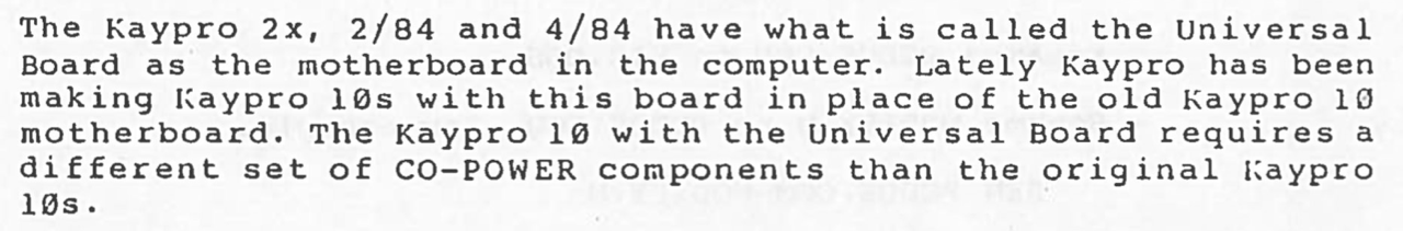
- Kaypro 10
- UNIVERSAL BOARDs
- Other
- ROM (Monitor & Character)
- Hard Disk Controller
- Interface Board
- Hard Disk Drives
- Floppy Disk Controller
- Floppy Disk Drives
- Video
- Power Supply Unit (PSU)
- Cabinet
- Keyboard
- Problems
- Downloads
- Information
- References
Overview
As of 04/02/2022 I am very sure that I have now found all known versions of the CP/M Kaypro's. Some Kaypro's (5, 10 pre) had disappeared from consciousness. But I have rediscovered them after a very long search on the internet.
In particular, I am a little proud of the rediscovery of the Kaypro 5. Even in the most important forum (VCF) in the USA, no member could tell me anything about this Kaypro -> My request in the VCF forum.
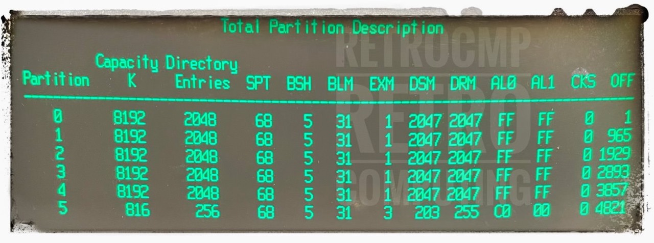
| NAME | MHz | MB | FDD | FDD | S | P | HDD |
|---|---|---|---|---|---|---|---|
| 1 | 4,0 | UL | 2x DS/DD, 390K | V, HH | 2 | 1 | -/- |
| II Kaycomp | 2,5 | -/- | 2x SS/DD, 191K | V, FH | 1 | 1 | -/- |
| II (V) *1) | 2,5 | -/- | 2x SS/DD, 191K | V, FH | 1 | 1 | -/- |
| II (H) *1) | 2,5 | -/- | 2x SS/DD, 191K | H, FH | 1 | 1 | -/- |
| 2 | 2,5 | -/- | 2x SS/DD, 191K | H, FH | 1 | 1 | -/- |
| 2/84 | 4,0 | UL | 2x SS/DD, 191K | H, HH | 2 | 1 | -/- |
| 2X | 4,0 | UL | 2x DS/DD, 390K | H, HH | 2 | 1 | -/- |
| New 2 | 4,0 | UL | 1x DS/DD, 390K | H, HH | 2 | 1 | -/- |
| 4 | 2,5 | -/- | 2x DS/DD, 390K | H, FH | 1 | 1 | -/- |
| 4/84 | 4,0 | UL | 2x DS/DD, 390K | H, HH | 2 | 1 | -/- |
| 4X | 4,0 | UL | 2x DS/HD, 2.6M | H, HH | 2 | 1 | -/- |
| 5 *2) | 2,5? | -/- | 1x SS/DD, 191K | V, FH | 1 | 1 | 5.5M |
| 10 (pre) | 4,0 | -/- | 1x SS/DD, 191K | H, HH | 2 | 1 | 8.9M |
| 10 ('83) | 4,0 | -/- | 1x DS/DD, 390K | V, HH | 2 | 1 | 8.9M |
| 10 ('84) | 4,0 | UL | 1x DS/DD, 390K | V, HH | 2 | 1 | 8.9M |
| 12X | 4,0 | UL | 1x DS/HD, 2.6M | V, HH | 2 | 1 | 8.9M |
| Robie '83, '85 | 4,0 | UL | 2x DS/HD, 2.6M | H, HH | 2 | 1 | -/- |
| Robie '83 *3) | 4,0 | UL | 2x DS/DD, 390K | H, HH | 2 | 1 | -/- |
(V = vertical / H = horizontal / FH = full-high / HH = half-high / SS = single-sided / DD = double-density / HD = high-density / UL = Universal Board / MB = mainboard / FDD = floppy disk drive / HDD = hard disk drive / S = serial / P = parallel)
*1) There are two variants of the Kaypro "II", with vertically or horizontally arranged full-high floppy disk drives.
*2) The Kaypro 5 is the hard disk version of the Kaypro II (vertical).
*3) I am very sure, there was a Robie version with double sensity drives for the European market.
Mainboards
The distinction between the Kaypros is actually quite simple. There are basically two major versions that were built.
- '83 models (pre-84)
- Kaypro II, 2 and 4
- Kaypro 10
- '84 models (UL)
- Kaypro 1, 2/84, 2X, New 2, 4/84, 4X, 12X, Robie
- Kaypro 10
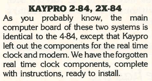
The '84 models (and later) are all based on the UNIVERSAL BOARD (UL) and have two serial and one parallel interface. If your Kaypro has only one serial and one parallel interface, it is a '83 model, either the Kaypro II, 2 or 4. Micro Cornucopia magazine also refers to the '83 models as pre-84.
Only with the Kaypro 10 ('83) and 10 ('84) you have to look directly at the mainboard because both have two serial and one parallel interface. Externally, you can not distinguish the two Kaypro 10.
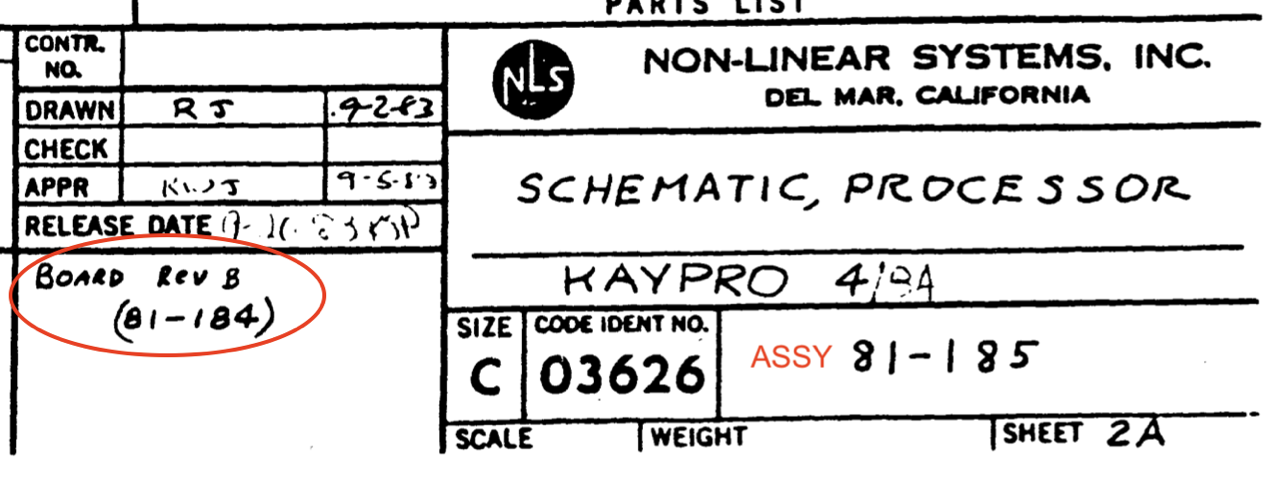
My Hypothesis About the PCBs and Mainboards
It is important to distinguish between mainboard (or ASSY) and PCB, especially with the so-called UNIVERSAL KAYPROs. The mainboard is the PCB plus assembly. The PCB is the pure board without assembly.
According to my researches there are basically five PCB's (but with revisions).
The actual part number (P/N) of the PCB can usually be found on the back. It is branded onto the PCB.
- 81-110
- REV A
- REV B (never seen)
- REV B1
- REV B2
- 81-240
- 81-180
- REV B
- REV C
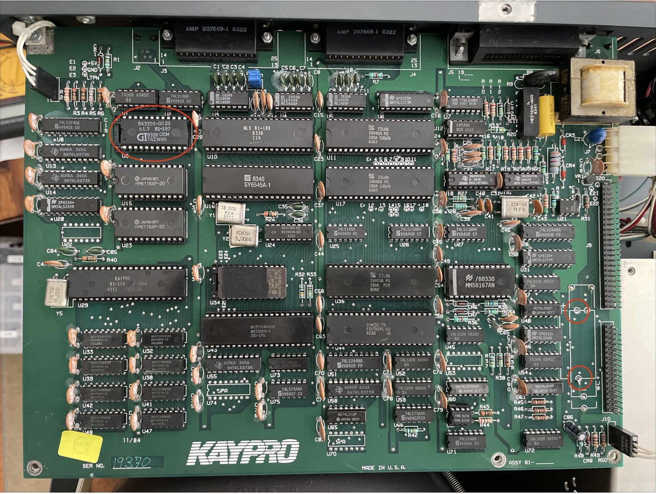
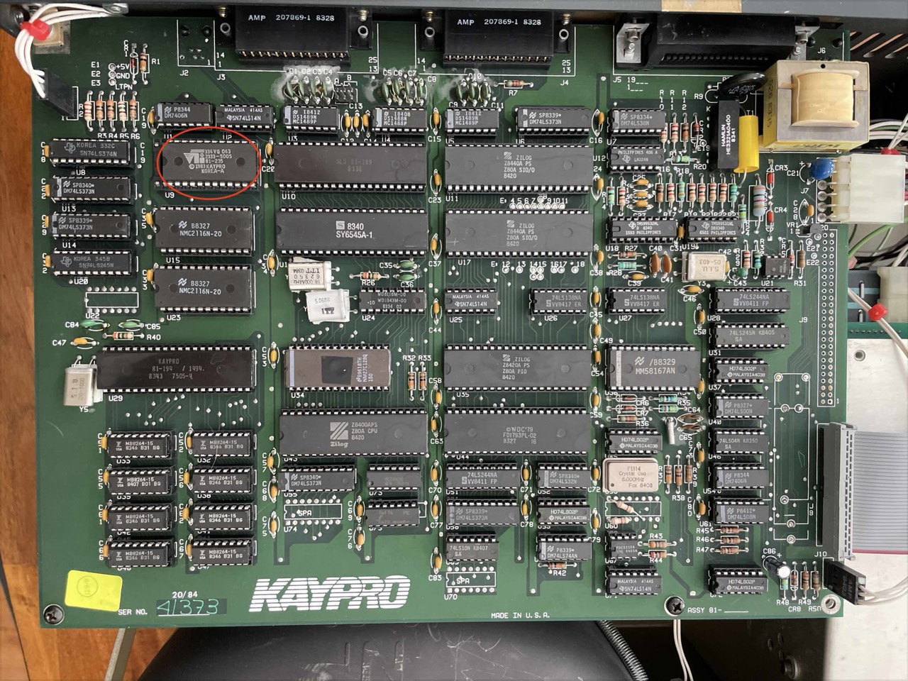
- 81-184
- REV A (no R53/C87 footprints)
- REV A1 (no R53/C87 footprints)
- REV B (no R53/C87 footprints)
- 81-470 (with R53/C87 footprints, not yet confirmed by picture)
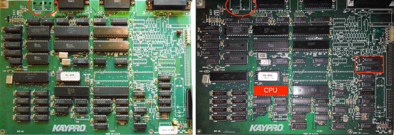
No. 1: Kaycomp II, Kaypro II, Kaypro 2
No. 2: Kaypro 2, Kaypro 4
No. 3: Kaypro 10 ('83)
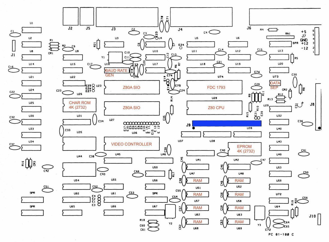
No. 4, 5: UNIVERSAL BOARDS, see Kaypro manual "F", pages 6-44, 6-50 and 6-56.

I have another 81-184 REV A1 mainboard, but without the components for the hard disc and RTC. It (presumably) comes from a Kaypro 2X.

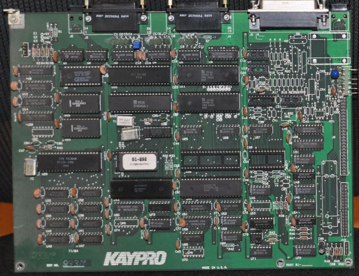
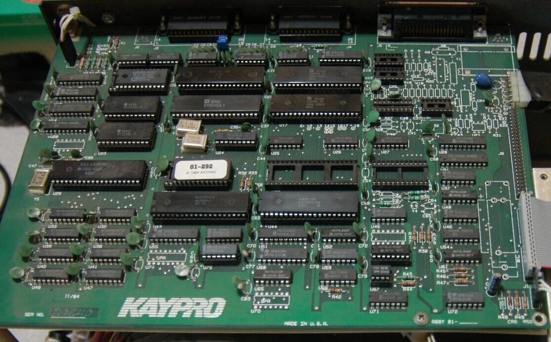
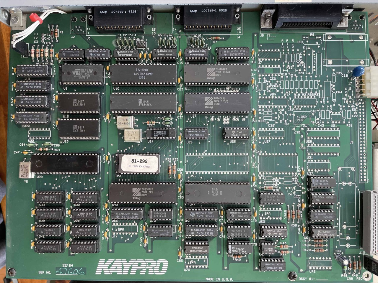
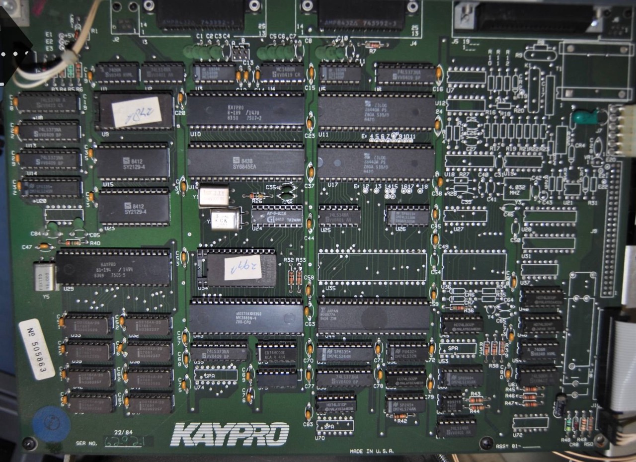
UNIVERSAL BOARD (UL)
The basic board layout of the UNIVERSAL BOARD is the same for all the '84 Kaypro (and all later) models. This concerns: 1, 2/84, 2X (r1, r2, r3), New 2, 4/84, 4X, 10 ('84), 12X and Robie. The differences of the various models are in the actual installed assemblies and the ROM BIOS. Kaypro has probably followed the principle here for commercial reasons: One mainboard for all.
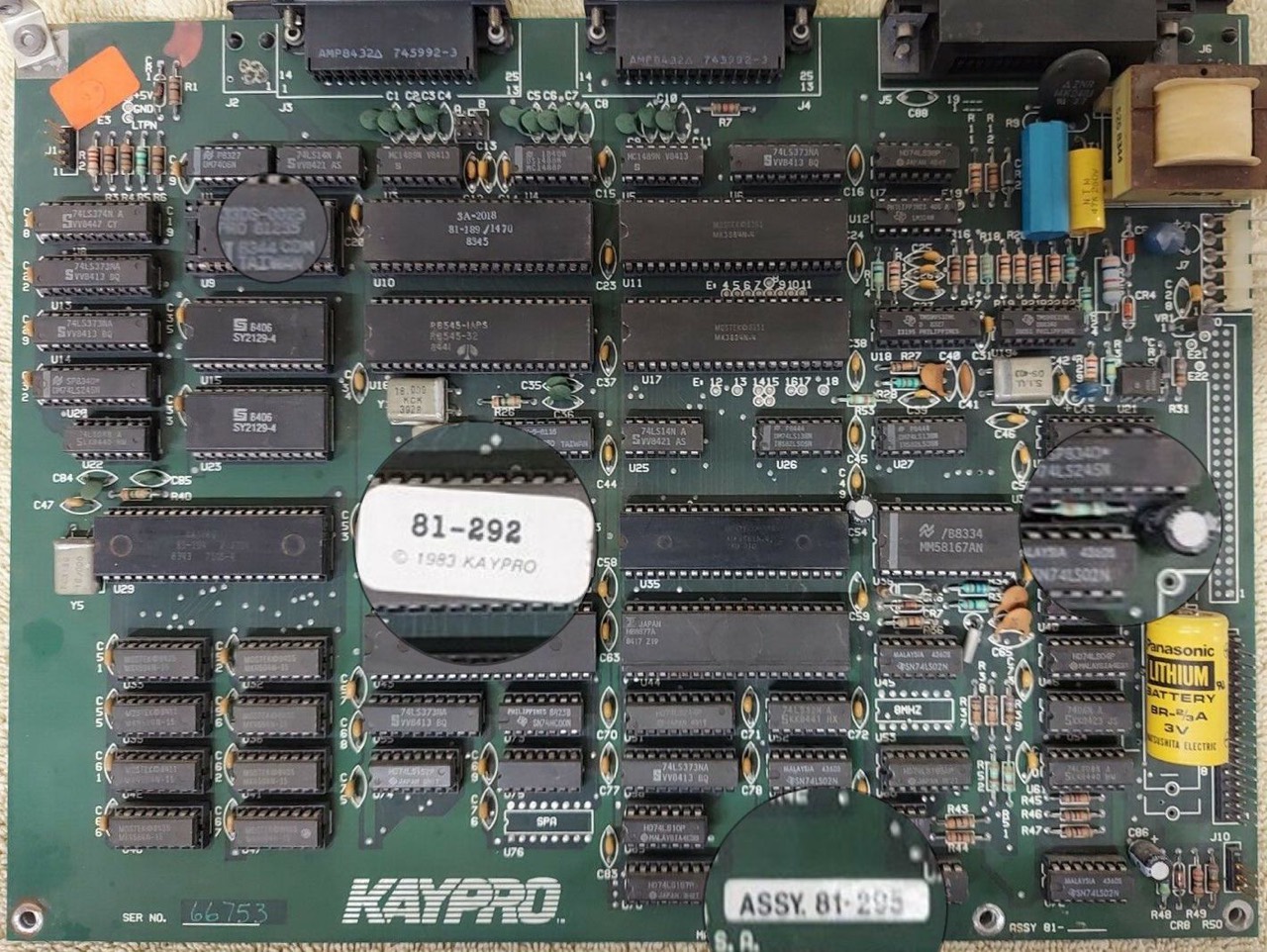
On the subject of UNIVERSAL: In my Kaypro Robie I have now tested three different ROMs without any problems. Among others the 81-292A (4/84) and the Micro C Pro-884 Max. Only with the Kaypro 10 ('84) you have to watch out. The ROM must of course support a hard disk.
What is really annoying is that Kaypro almost never specified an ASSY on the boards.
Marc Wilson, 1990: Kaypro made two motherboards that support the hard drive interface. These were the 81-180 board (the Kaypro-10 board), and the 81-185 board (the 2/84-4/84-2X-Robie board). The 81-185 board has several different part numbers, depending on which machine it was installed in, whether or not it had the real-time clock installed, the modem installed, etc. The 81-185 board is also where the dreaded Universal ROM made it's appearance. Not to worry, the same board can also run the normal 81-302 ROM.
The 81-184/185/294/295/296/580/582 motherboards are all the SAME motherboards, and they all support the HD. The best of these to have is the 81-184/185, because it also includes the RTC and the modem. This motherboard is also known as the Universal Motherboard. [56]
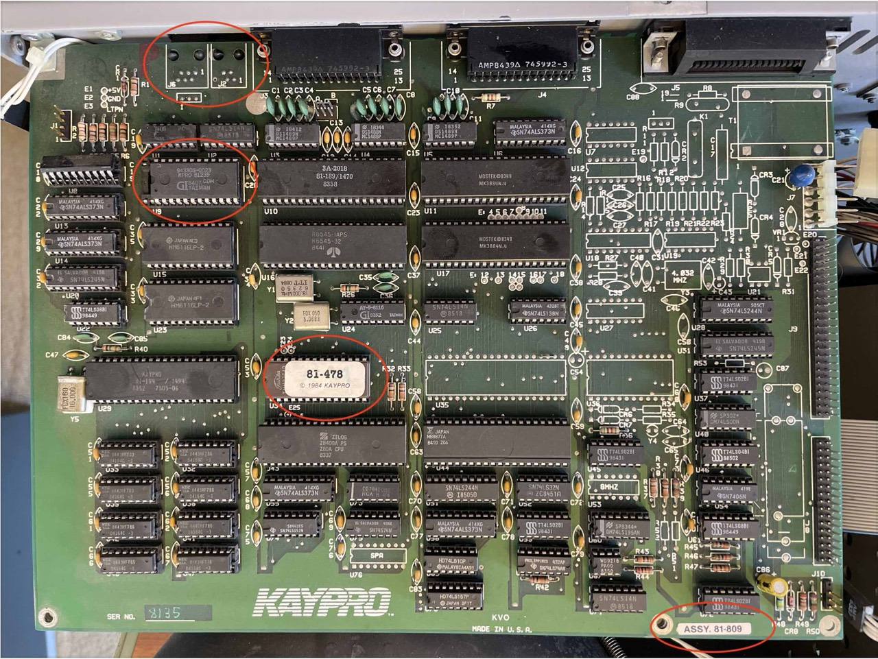
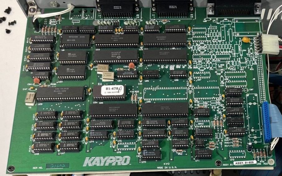
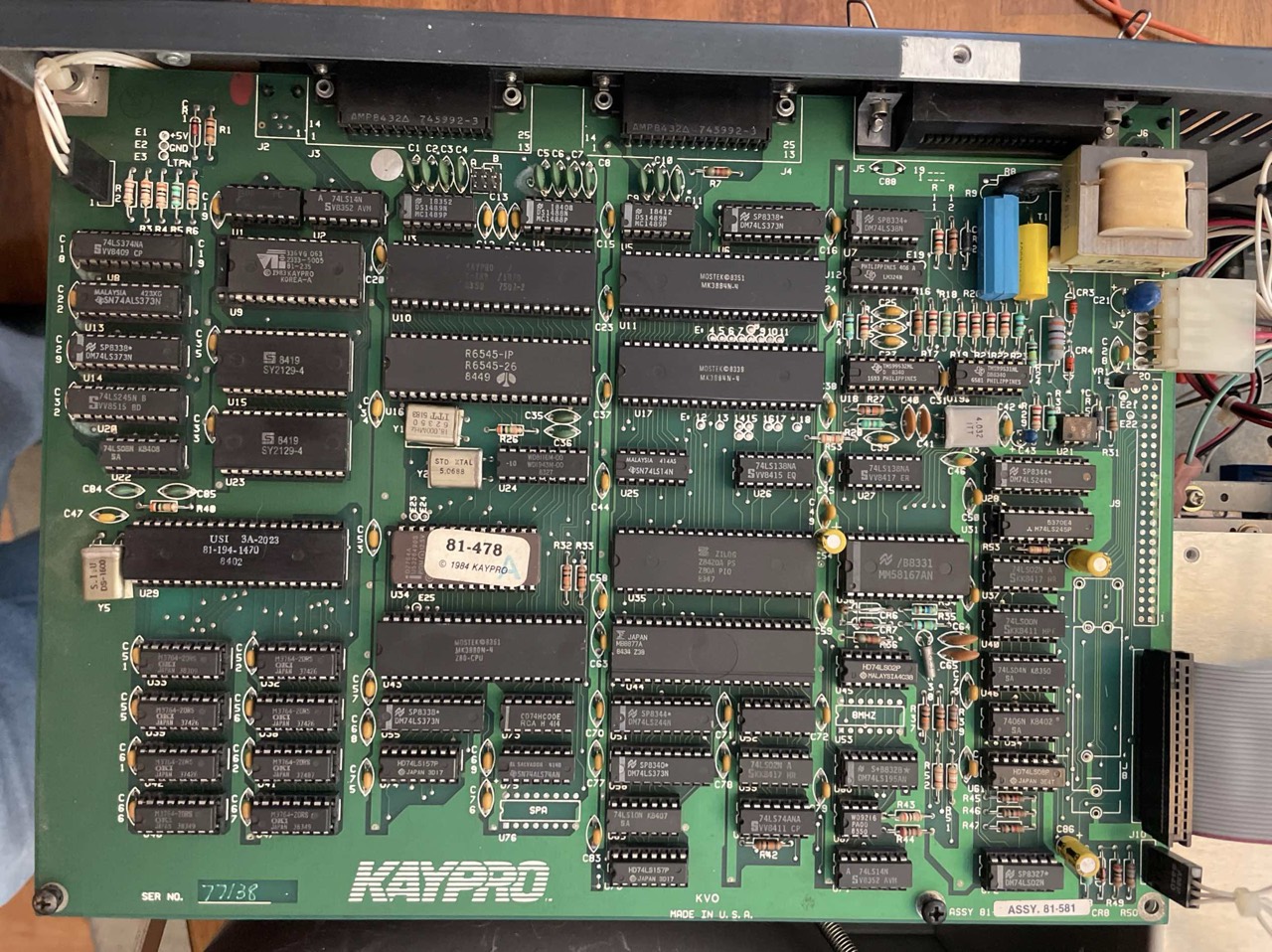
The UNIVERSAL BOARD is not to be associated with the terms UNIVERSAL BIOS or UNIVERSAL ROM or UROM. BOARD and BIOS are two different things. Some say that only when the UNIVERSAL BIOS is used it is also a UNIVERSAL BOARD. But I think this statement is wrong. The UNIVERSAL BOARD is equipped with different BIOS versions depending on the specific Kaypro model. One amongst others is the ROM version "81-478" (in combination with CP/M version 2.2ul), colloquially also called UROM or UNIVERSAL BIOS.
There are always discussions in the forums about which Kaypros have a UNIVERSAL MAINBOARD. Just look in the Kaypro documentation and others, it is written there "in black and white". Basically the Kaypro 1 and the New 2 must be added, both have also a UNIVERSAL BOARD.

(2 = 2/84, 4 = 4/84)
For this reason, the UNIVERSAL BOARDs appear in the most diverse variations. Only the Kaypro 10 ('84) and Kaypro 1 have a "special" feature. Here, the two RJ45 connectors are arranged directly next to each other - seen from behind - on the right. Since the Kaypro 1 was the very last model, they probably took the Kaypro 10 ('84) UNIVERSAL BOARD and left out the modem, real-time clock and hard disk interface. And finished is the Kaypro 1. You only need a new cabinet.
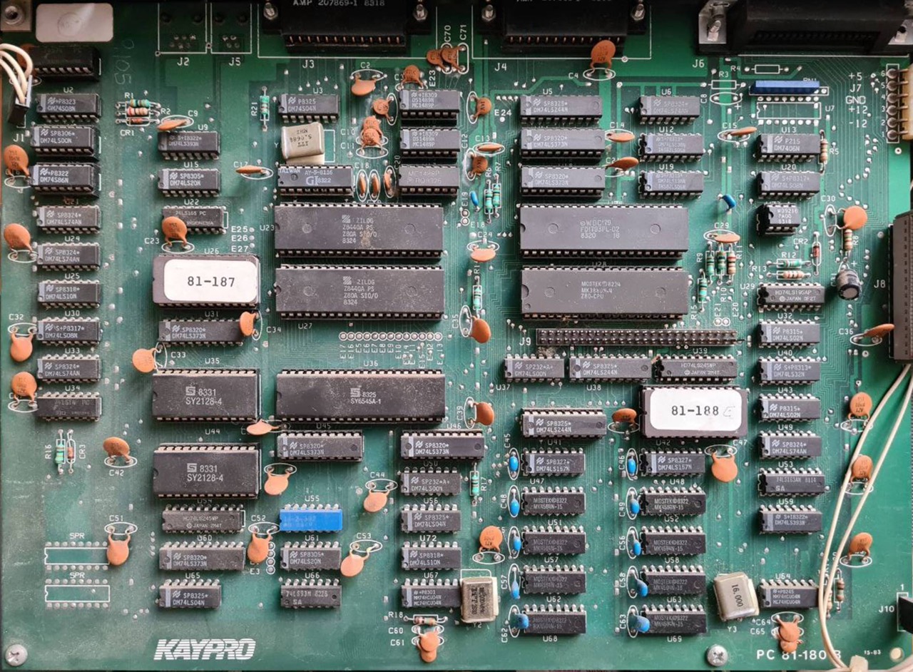
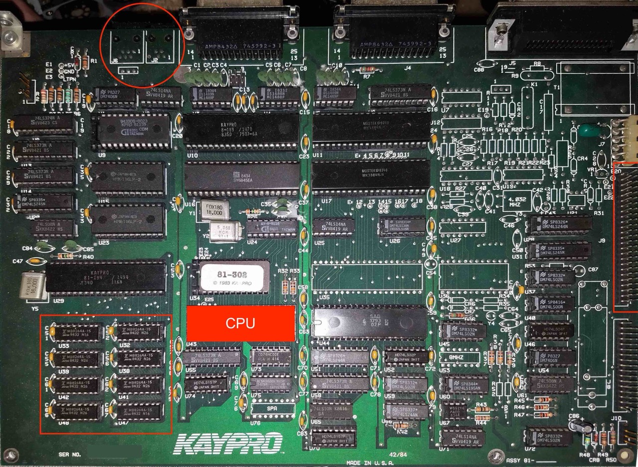
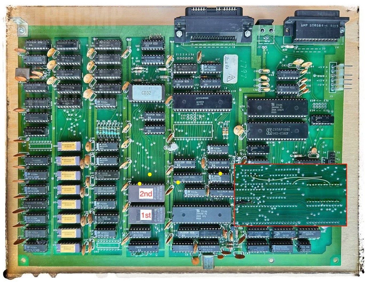
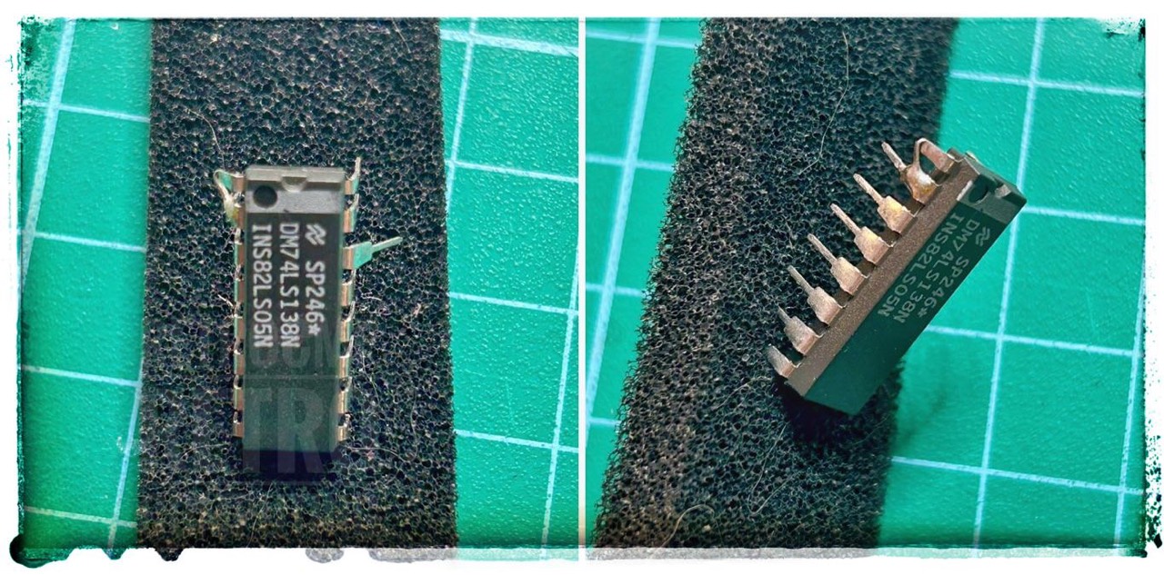
KAYPRO UNIVERSAL BOARD - This board is the most common of the '84 series computers. It can be used in almost all of the later model 8-bit machines. The board has two RS232, one Centronics parallel, one 6 pin modem, and one keyboard connector. The modem and keyboard connectors are at opposite ends of the board. The board will have spare socket locations at U70 and U74. The board may also be missing almost all of the components near the Centronics connector on the Kaypro 2 models. Hard drives may be connected at J9, which is located between the power and the floppy disk interface connectors, on the edge of the board. J9 may not be installed. The ROM and character generator sockets are both 28 pin sockets, which can address ROMs as large as 2764's without modification. [11]
From the following quotation it can also be concluded that the Kaypro 10 ('84) is also available without a modem. To confirm this, see the pictures of the Kaypro 10 ('84) mainboard below.
Kaypro 10 ('84) [, Kaypro 1] - This board is almost identical to the UNIVERSAL BOARD, except that the modem and keyboard connectors are right next to each other. There will be a spare socket located at U76 on this board. The modem connector will not be connected to anything unless the modem components are installed. [11]
The ROM socket U34 can be equipped with 4K (24 pin) as well as 8K (28 pin) EPROMS. The two RJ45 plugs are located on the left and right. But there are also some subtle differences in the UNIVERSAL BOARDs. The board is available both with and without R53/C87; bottom left next to J9. Take a closer look at the following pictures of the boards. At first glance, one might think that this is directly related to the presence of U36 (clock IC). But this is not the case, see 4/84 and 4X. Further information on this topic can be found in the TCJ magazine, issue #64 on page 14.
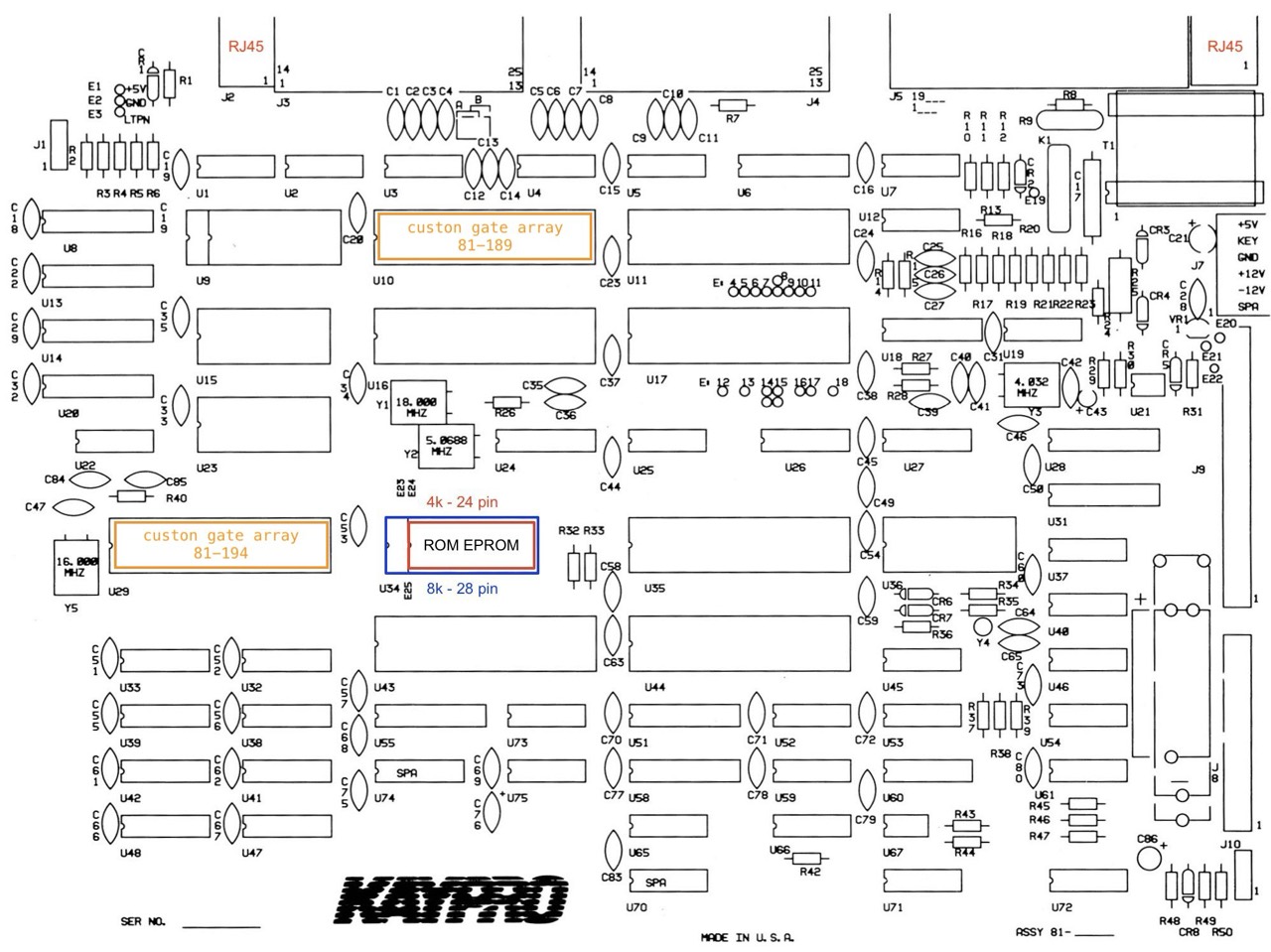
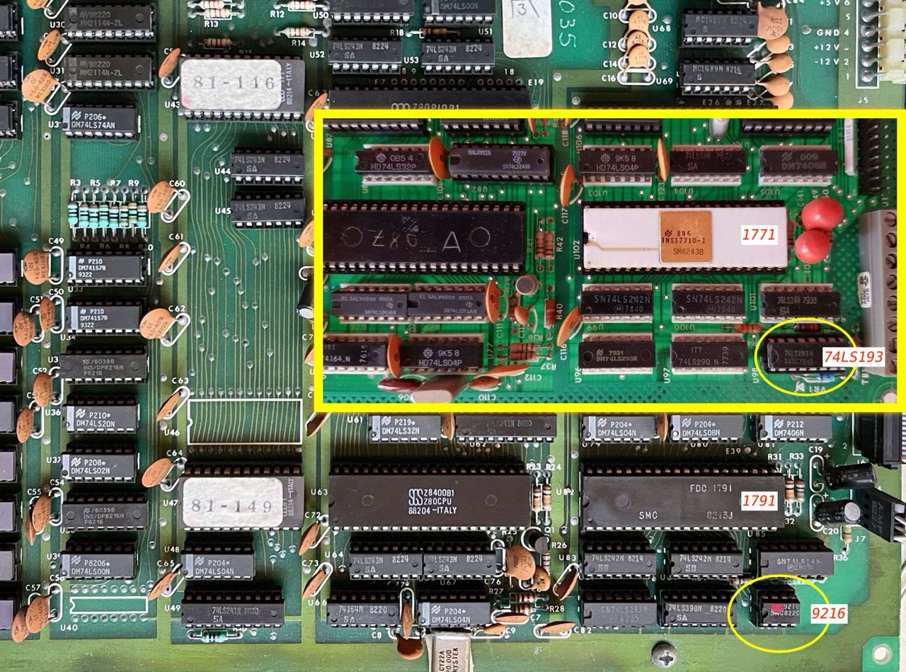
About U29: The equivalent circuitry can be inferred from looking at the Kaypro 10 schematic, with a little effort. The Kaypro 10 original mainboard was effectively a prototype for the two custom LSI chips [U29, U10] Kaypro later produced for the 2/84 and beyond mainboards. One is for DRAM control and the other is for CRTC. [92]
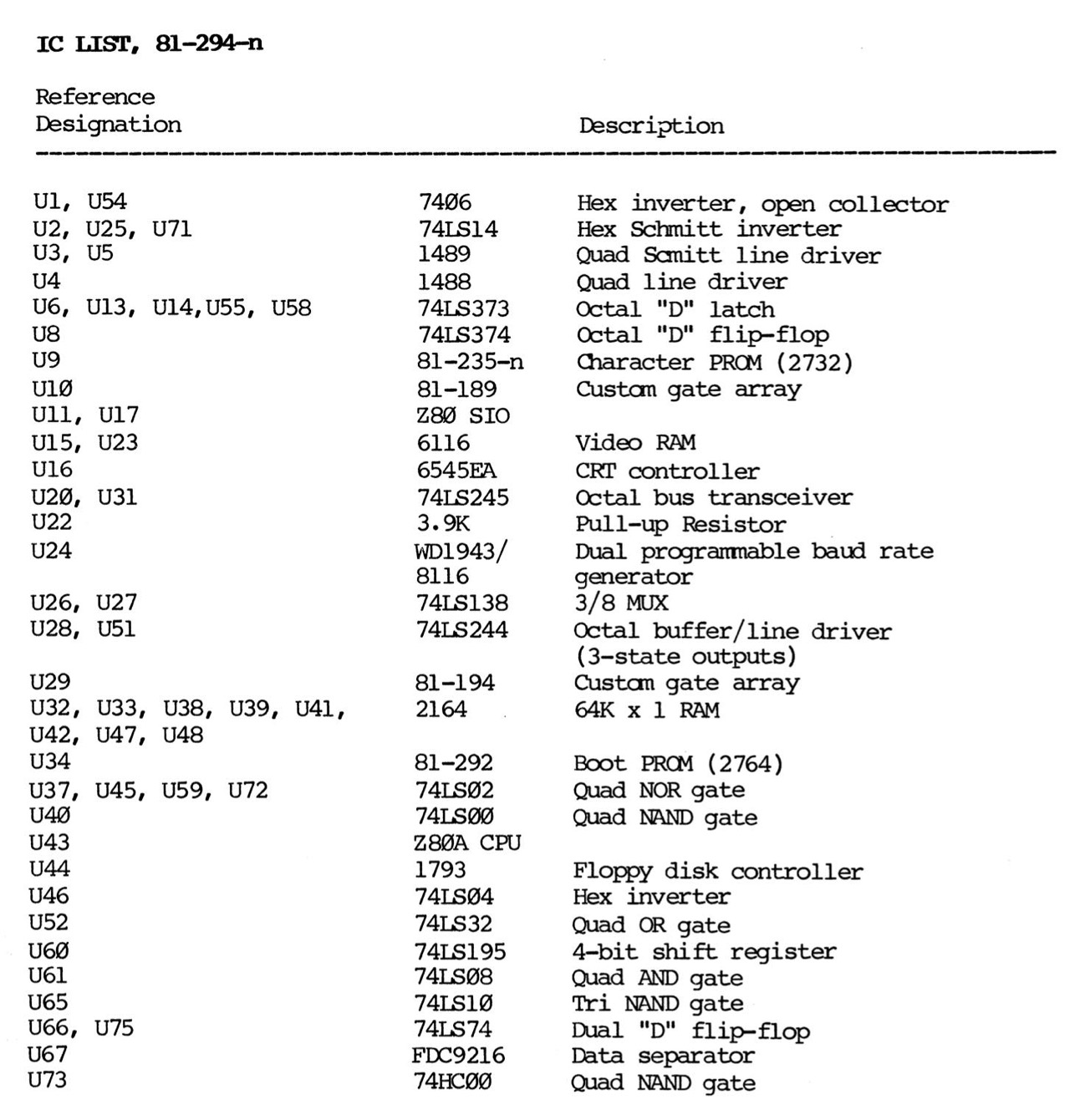
Sections: BLUE - video ; GREEN - I/O ; RED - CPU ; WHITE - missing in the official Kaypro IC lists. [65] And here is the corresponding IC list as a pdf spreadsheet. I have made an effort (with both), but of course mistakes cannot be ruled out!
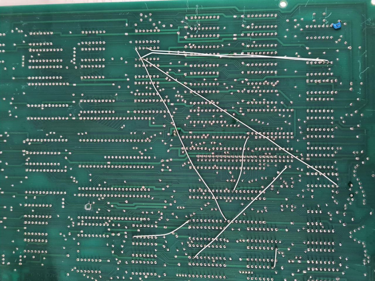
The two additional cables to connect the modem (secion) to the RJ45 connector are well visible; R53 and C87 are present.

I don't have better pictures, but you can see very well that basically the Kaypro 1 and the Kaypro 10 ('84) use the same UNIVERSAL BOARD but with a different assembly.
In the next picture(s) you can also see that the Kaypro 1 (ASSY 81-809) is equipped with an 8K BIOS (81-478) and the Kaypro 10('84) only with a 4K BIOS (81-302).
You can also see very clearly the two additional ICs that are necessary for the operation of the hard disk. Don't let yourself get confused. In the right picture the CPU is missing, I have added it!
Two Revisions of the UNIVERSAL PCB's
Based on my research, I have found out that there are basically two PCB revisions. The older one, revision 1 is installed in the Kaypro 2/84, 2X r1, 4/84, 4X and Robie according to the information (pictures) I have. Revision 2 is installed in the Kaypro 2X r3, 10('84), 12X and 1.
I found a total of seven areas on the PCB that are different, see next picture; please do not disturb by the actual assembly.

The following variants (by the example of R53/C87) are possible:
- (1) no footprints
- (2a) footprints but not populated
- (2b) footprints and populated
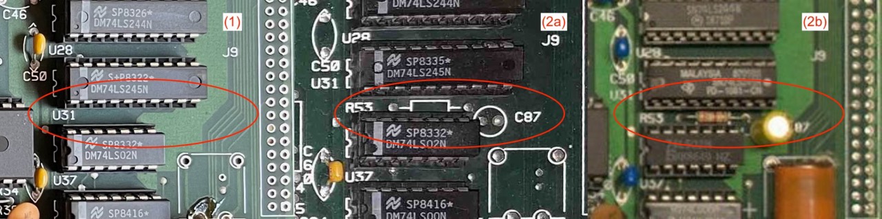
Variant (1) and (2) are different PCB's; variant (2a) and (2b) are the same PCB's (revision 2).
I can say with certainty, because it is my board, that variant (1) can be found on the PCB numbered P/N 81-184 REV A1. PCB version 81-184 REV B is fitted in the Kaypro 4/84 and has also no footprints (variant 1), see below.
Also confirmed by pictures is that both variants (2a) and (2b) can be found in the Kaypro 10 ('84). These should be PCB 81-470, see my comments about the PCB's.
Based on the information I have, the following is the result (yes = with footprint; rn = revision n; HD = high density):
The result is interesting in that the Kaypro 1 came out after the 10 ('84) and both have the RJ45 connectors right next to each other! This confirms my assumption that both have the same PCB, only the assembly is different. See above.
But here again the note, in the Kaypro manual "F" the information is not always conclusive!
Some Information about C87 and R53
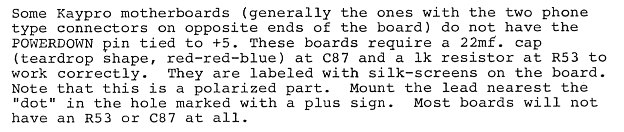

Upgrading the RTC and Hard Disk Interface Parts
If your UNIVERSAL BOARD is not fully populated you can do it by yourself if you have some soldering skills. Just follow this link.
Kaypro 1
The UNIVERSAL BOARD is basically installed in the Kaypro 1; R53 and C87 footprints are but not populated.
The following mainboard is missing or not installed: real-time clock, battery, modem. The two RJ45 plugs are located side by side on the upper left. This arrangement is otherwise only found on the Kaypro 10 ('83) and 10 ('84)!
Here, it is noticeable that the hard disk section is populated, although the Kaypro 1 does not have a hard disk.
Kaycomp II
Kaycomp II - This board [81-110A] is found in the very early Kaycomp's and Kaypro's. It has one serial RS232 connector, one Centronics parallel connector, and one keyboard connector on the back. The board has sockets (only one is installed) for two 2716 ROMs, and a CTC chip. The floppy controller chip is probably a 1791. This board also has a hardware scroll register (not used by the software), that may cause the later versions of Uniform to confuse the screen. [11]
This statement is consistent with my research on the 81-110A and 81-110B1/B2 boards. See Kaypro II, MB 81-110A
Kaypro II
The Son of the Ferguson Big Board I
The similarity of the first Kaypro board (81-110-A) with the Ferguson Big Board I is discussed in issue 15 of Micro Cornucopia from December 1983: Son of a Big Board.
The KayPro II portable microcomputer manufactured by Non-Linear Systems is based on the Big Board. They made a few changes to the board. They used 4164 RAMs, the keyboard outputs serial data to port B of the SIO, and they changed the 1771 to a 1791 for double density (5"). The board has space for the CTC timer and for all four EPROMs but there is a socket for monitor ROM only. The KayPro documentation shows that the memory map is identical to the BB. Very interesting. [44]
In many ways this [Kaypro II] is a Big Board. The processor clock circuit is the same, as is the processor and much of the RAM select. However, the RAM chips are the 64K devices and the video circuit has been changed slightly. In the video circuit, the hardware scroll circuit has been removed along with the composite video output. The output is standard separate TTL level signals. In part, even the board layout is the same but because of the 64K chips, the board is substantially smaller. [I am still looking for]
In the August 1983 issue #13 of Micro Cornucopia, David J. Thompson says on page 39: "... the Kaypro [II] is 95% identical to the Big Board I ...".
Now look at the following two pictures. The similarities of both boards are enormous.
I am not aware of any lawsuits between Ferguson and Kaypro regarding the mainboard. I only know from David Kay that at first it was an option to use the BigBoard I, similar to the Xerox 820. But Jim Ferguson did not agree to use it.


In large parts the arrangement as well as the type of the TTL and other components are identical! The CHARACTER ROM (Kaypro, U43, 81-146) was also adopted 1:1, as reported by David J. Thompson in his Micro C magazine in December 1983. [75]
I sent a copy of my character ROM to Non Linear (after getting a non-copying agreement from David Kay). They have upgraded their characters [81-146-A] somewhat since receiving mine but they haven't gone all the way with it. [75]
Long story short, NLS/Kaypro not only presented the Kaycomp II (Osborne-like) with an original Ferguson Big Board I at the trade show in March 1982 (only insiders knew this), but also the first Kaypro mainboard (81-110-A) was almost identical to the Ferguson board. According to David Kay, a young junior technican designed this board. All other senior engineers were working in the analog field at NLS at that time. At that time Bill McDonald was the senior engineer in charge of the Kaycomp II. [76]
I have not yet been able to find out the name of this young technician. David does not remember the name.
The Ferguson board uses the FD1771 (with internal data separator and FM only) while the 81-110-A already uses the FD1791 (needs an external data separator, FM and MFM). In the later boards 81-110-B/B1/B2 the FD1793 was used. Note: "The FD1793 is identical to the FD1791 except the DAL lines are TRUE for systems that utilize true data busses." [47]
The following statement overlaps in time with the information I got from David Kay. In the first months (1982) there was no finished Kaycomp that NLS could deliver! And yes, the mainboard used in the Kaycomp II at that time was the BigBoard I, which had only a FM controller!
Encouraged by the sales of Osbome's computer, Kay increased the production schedule on the Kaypro II four times during the first months of 1982. He was ready to ship 100 units in May but held off for a month so that the disk drives could be converted from single to double density. Then, in June 1982, he began selling the 26-pound Kaypro II. [77]
Important questions: At the end of the WCCF (03/21/1982) there was only the Osborne alike prototype, the mainboard (81-110-A) had not yet been fully developed and there was no functioning BIOS. There were only 50 working days (10 weeks) to the actual sales launch on 1 June.
How can 100 computers that could have been delivered in May be converted from single to double density? Well, if it had really only been the floppy disc drives, then it would have worked (Shugart 400L to Tandon TM 100-1A); no problem. But then the mainboard would have had to have the FD1791 and the FDC9216. I can't imagine it any other way. Converting the mainboard and changing the production process would have been far too time-consuming. Well, the puzzle will probably not be solved.
MB 81-110
The 81-110 PCB is used in the early Kaypro II models up to serial no. 25,000 [73]. The later "II" models but use the 81-240 PCB, which is also used in the Kaypro 4 ('83).
The labeling of the 81-110 PCB is on the solder side. You can also reliably recognize this board by the labeling of the ROM (U47). This is marked with 81-149 or 81-149-A/B/C.
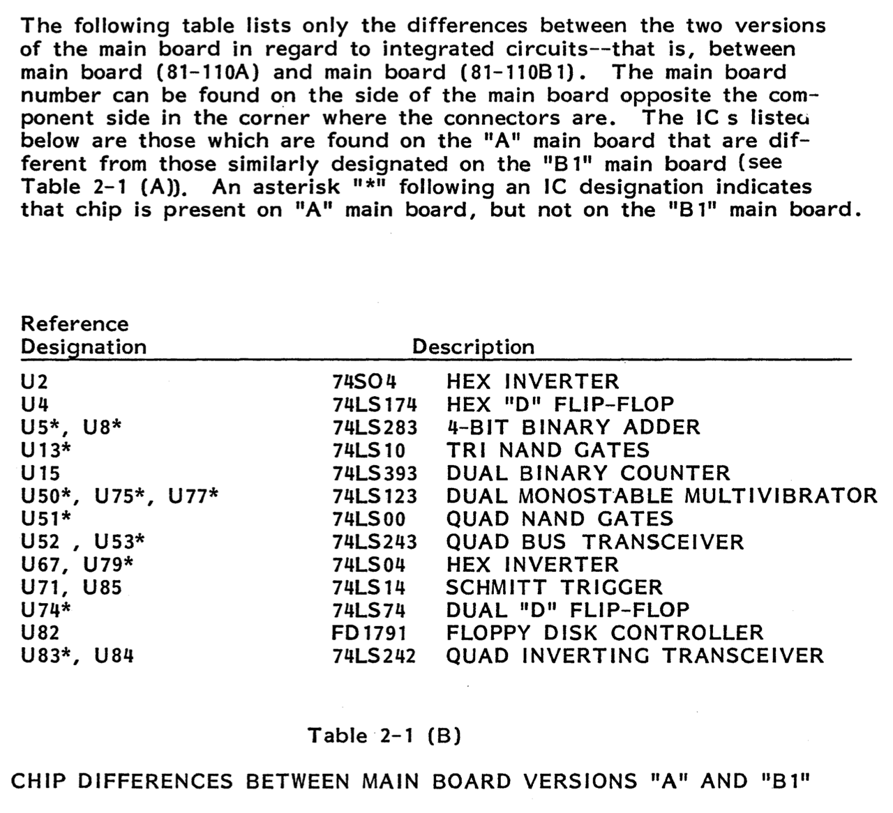
According to [45] and [73] the 81-110 PCB exists in four revisions A, B, B1 and B2; and there are again two subrevisions of the "B1" board; see next list (3A, 3B).


- 81-110A
- U46 (not used, 2nd 2716 ROM)
- U55 (not used, Z80 CTC IC)
- U2 and U67 are TTL
- FD1791 (inverted data bus)
- Q1, C6 existing
- 11 additional ICs (see below)
- 81-110B
- ... never seen in the wild ...
- 81-110B1
- U2 & U67
- TTL
- CMOS
- FD1793 (true data bus)
- Q1, C6 missing
- 81-110B2
- U2 and U67 are CMOS
- FD1793 (true data bus)
- Q1, C6 missing
Furthermore, the variant "A" is characterized by the fact that the floppy controller from Western Digital is of type 1791. The following models but all use the type 1793.
The FDC 1793 is identical to the FDC 1791 except the DAL lines [DATA ACCESS LINES] are TRUE for systems that utilize true data busses.
[DATA ACCESS LINES, DAL0-DAL7] Eight bit bidirectional bus used for transfer of data, control, and status. This bus is a receiver enabled by WE or a transmitter enabled by RE. The Data Bus is inverted on the FDC 1791, FDC 1792 and FDC 1795. [47]
As for the Western Digital FD1791 floppy controller, I found absolutely nothing else in the Micro Cornucopia magazines. The only reference comes from the magazine BYTE from September 1983 on page 213. Here only the 1791 is mentioned, but the picture of the Kaypro II mainboard is of type "B1", so actually with 1793!
The difference between mainboard A and B1/B2 is very striking; you can't really confuse them. In the next picture you can see variant "A" on the left and variant "B2" on the right. The difference TTL - CMOS is of course not visible. Note: Please don't be confused by the ROM and modifications on the right; it is basically a "B2" motherboard.
Here you can also see the difference between the WD1791 and WD1793. A second 74LS242 (quad inverting tranceiver) is installed at U83 (right to the red circle).

Another difference between 81-110 "A" and "B1/B2" is the pull-up circuit. In the early "A" version the transistor Q1 and the capacitor C6 are present, in the later "B1/B2" version not, see red circle. Why? By replacing U67 (74LS04) with a faster 74HC04, Q1/C6 are no longer needed. [32]
In the I/O section around the floppy controller WD179X you can see very clearly the savings between the A and the B1/B2 mainboard. In total there are five IC's (U74, U75, U77, U79 and U83) missing.
According to Micro Cornucopia issue 14, page 2 from October 1983, the first mainboards - up to serial number ~ #30,000 - still had the Q1 pull-up transistor installed in the Z80 clock circuit.
Q1 and C6 are missing in the later models (> ~ #30,000). I have a Kaypro II with the serial number #34,644 and have the version "B2", CMOS ICs (U2, U67) and no Q1/C6.
This issue (MC #14) also explicitly mentions the "old A" mainboard. Furthermore, David Thompson writes that this "old" board can also be tuned in terms of speed and other mods, see below.
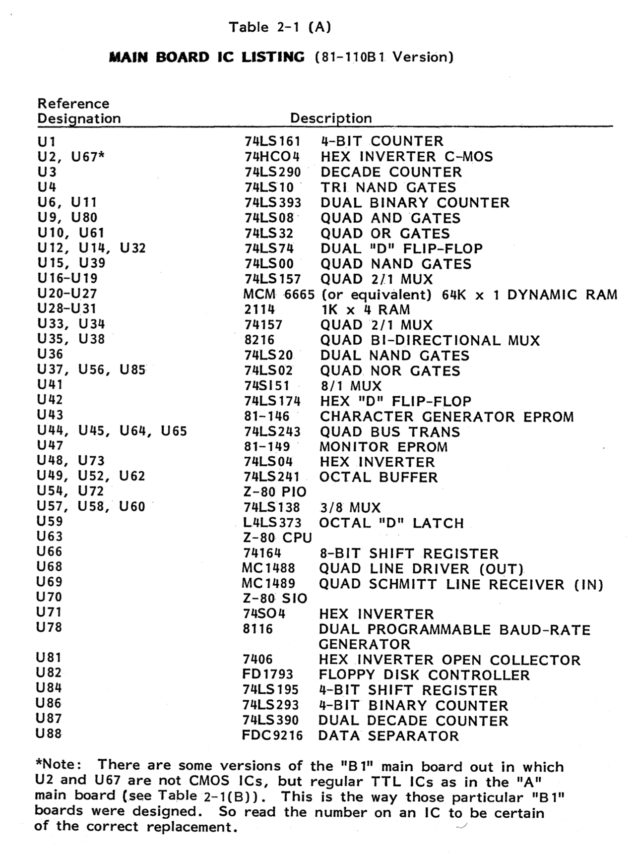
So far I have not found a schematic for the 81-110-A motherboard. Currently, I am only aware of the technical manuals in versions C through F. However, only version "B1" is always included here. Possibly, however, the manual versions A and B with the mainboard version "A" still exist in some old bookcase, who knows.
That the following mainboard is a very early version can also be seen in the ROM. It still uses the 81-149 and not the subsequent version A, B or C. Whereby the version A and B are also seldom. No DRIVE FIX MOD at U87. I will do that later.
There are two missing sockets on this board: U46 is not used for a 2nd 2716 ROM; U55 was originally intended for a Z80 CTC (counter/timer circuit) [11] ; see Ferguson BigBoard I. Both spare sockets are no longer present on the later B1/B2 mainboards. If you are curious, you can install both of them. The PCB tracks are present and connected.
I have the Kaypro II scheme from Micro Cornucopia dated 23.05.1983. U46 and U55 are not shown here. On the other hand, C6 and Q1 are indeed shown (dashed) with the note: "present only on early models".

(Do not mind the missing 8116/U78)
In the next picture, if you look closely (red circle), you can see an incomplete, subsequently restored conductor path. I looked at the circuit board through the light. The conductor path is indeed incomplete. No DRIVE FIX MOD at U87. I will do that.
MB 81-240
According to Micro Cornucopia (issue 14 of October 1983, page 20), the small ICs were soldered directly in the mainboard from October 1, 1983. Before that, they were socketed, which made replacement very easy.
According to this statement the following mainboard (#102,817) belongs to a Kaypro after Oct 1983 because many ICs are not socketed.
At the same time [10/01/1983], Kaypro began shipping the Kaypro 4 ROM (a 2732A) on both the Kaypro II and Kaypro 4 so you shouldn't need a new monitor ROM to go 5 MHz. Also, all it should take to turn your Kaypro II into a Kaypro 4 are two double sided drives and a copy of someone's 4 system disk. ... [42]
The Kaypro II will have the original Kaypro 4 board and ROM. In fact, the present Kaypro II and 4 systems have a simple monitor sign-on that says "Kaypro" rather than Kaypro II or Kaypro 4. That way they can use the exact same board [81-240] and ROM. [38]
Although the case of my Kaypro proclaims it to be a II, it has a Kaypro 4 motherboard, ... [66]
Based on this information, I personally come to the conclusion that the 81-240-A mainboard with the 81-232 ROM is always a real Kaypro 4 ('83) mainboard. However, if it is installed in a Kaypro II cabinet with single-sided Tandon disk drives, it behaves exactly like a Kaypro II. From the outside, you cannot notice the difference. See also [50, p.15]
Kaypro 2/84
The UNIVERSAL BOARD is basically installed in the Kaypro 2/84; R53 and C87 footprints are not present.
Especially in this picture you can see that Kaypro has installed everything that was in stock. There are sockets installed, but they are/were not needed. The hard disk section is populated although the 2/84 does not have one.
Kaypro 2X
Revision 1
The UNIVERSAL BOARD is basically installed in the sticker Kaypro 2X (Rev1); R53 and C87 footprints are not present.
Revision 2
The UNIVERSAL BOARD is basically installed in the Kaypro 2X (Rev2); R53 and C87 footprints are not present. As revision 1.
Revision 3
The UNIVERSAL BOARD is basically installed in the Kaypro 2X (Rev3); R53 and C87 footprints are present and populated. Here the battery is removed.
The following motherboard gives me a few puzzles. The ASSY is 81-295, so it should belong to a 2/84, 2X-r1 or New 2. But all three have no modem and no real time clock. It's not really a 4/84 either, because R53 and C87 are equipped and J9 is missing. It could be a 2X-r3; RTC, modem, R53 and C87 fit, but the ROM 81-292 is installed and the ASSY is wrong. The 2X-r3 should have a 81-478 ROM! The board is probably a thrown together construction. Basically it fits into a Kaypro 4/84 or 2X-r3 because both have a modem and RTC.
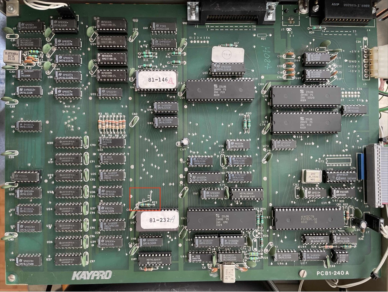
Kaypro 4('83)
You can usually recognize this mainboard/PCB by the number 81-240 A and the ROM version 81-232. This mainboard also has only one parallel and one serial interface. This board is also used in the later Kaypro 2.
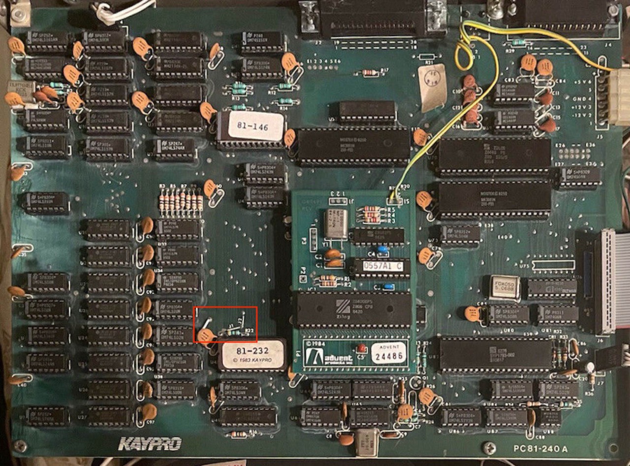
The mainboard above is an early version of the 81-240 because all ICs are socketed. The mainboard below is a later version because many ICs are not socketed, for example the RAM, U20 to U27.
The Kaypro II will have the original Kaypro 4 ['83] board and ROM. In fact, the present Kaypro II and 4 systems have a simple monitor sign-on that says "Kaypro" rather than Kaypro II or Kaypro 4. That way they can use the exact same board and ROM. [38]
Kaypro 4/84
The UNIVERSAL BOARD is basically installed in the Kaypro 4/84; R53 and C87 footprints are not present.
This motherboard is indeed UNIVERSAL because all components are populated. On the following board the battery was removed. Basically the 4/84 has a battery. Here, too, it is noticeable that the hard disk section is populated, although the Kaypro 4/84 does not have a hard disk.
Close Look at the New Kaypro 4 [4/84]: I had heard that the new Kaypro 4 had a Kaypro 10 board, two 390K drives, plus a battery backed-up timer and modem. Whee! It turns out that the new 4 board is more than just the 10 board with two additions. It contains two new 40-pin ICs that replace a lot of standard TTL chips. One of them is dedicated to the video section and it looks like the graphics department just got a lot smarter and easier to use (is someone planning 1,2,3 for the Kaypro?). All the Kaypros will soon contain this new board and meanwhile they've just dropped the price of the Kaypro II to $1295 (and the board is running 4MHz besides!). [41]
You could actually make a Kaypro 10 ('84) out of this board. But beware. You can only use "one" floppy drive if you have a hard disk! This is due to the fact that the hard disk controller uses the floppy DRIVE B SELECT signal as a RESET signal for the hard disk.
It's interesting to compare the original Kaypro II and 4 with the new 84 versions [4/84]. Of course, the new boards run faster (4 MHz vs 2.5 MHz) and they are fancier (graphics and all). But the new boards have a problem. You see, the new 84 boards have no buffers on the address and data lines, at least not until you get to the SASI (winchester) interface. There 11 inputs hanging directly on each data line on the original Kaypro 10 and 13 inputs on each line on the new 84 boards with the modem. The Z80 was not meant to drive that many inputs. [39]
Kaypro 4X
The UNIVERSAL BOARD is basically installed in the Kaypro 4X; R53 and C87 footprints are not present. On the following board the battery was removed. Basically the 4X has a battery.
According to an internal Kaypro memo, the 4X is the successor to the Robie. Since the Robie, according to the information available to me, ran very poorly, the familiar housing was probably used again. However, this did not solve the problems with the Drivetec drives. These drives were way ahead of their time, but unfortunately not reliable.
The KayPro 4X is the Kaypro Robie in an upgraded Kaypro 4 case. The reasons for installing the Robie in the Kaypro 4 case are cosmetics. [93]
Kaypro 10('83)
You can immediately recognise the Kaypro 10 ('83) mainboard by the J9 hard disk connector and the position of the RAM. The RAM (4164 class RAM, 64 by 1 bit) is not socketed! The two RJ45 plugs (J2-light pen, J5-keyboard) are located side by side on the left. This arrangement is otherwise only found on the Kaypro 1.

J2 (lightpen) with four solder points
J2 (lightpen) with six solder points
In the following picture(s) you can see "eight" differences between mainboard B (left) and C (right).
But there is also the variation with 81-180-B mainboard and 81-302-C ROM; I have a picture in my archive. At Kaypro, everything was installed that somehow fit together!

### Update 10.12.2021: One of the pins of the 34-pin floppy plug (J8) broke off today, it was only a matter of time. So I replaced the defective connector on the mainboard with a proper one. And since I had already heated up the soldering iron and desoldering gun, I also replaced the capacitors C31 (16V, 47uF) and C40 (104M (0,1 uF, 100nF), 12V).
More than two dozen of these brown 104M disc ceramic capacitors are soldered to the mainboard. I actually only replaced capacitor C40 because it was bent over a lot by the EPROM modification. A test with the capacitance meter showed a value of 108 nF. In other words, the capacitor still works perfectly. I therefore assume that the remaining 104M are also still OK.
Months ago, I was able to buy a whole package of almost identical looking 104M ceramic capacitors on eBay (US). On the German market, these brown disc ceramic capacitors with 12V and 100 nF are hard to get. So far I have only been able to find some with 25V; of course you can use those too. ###
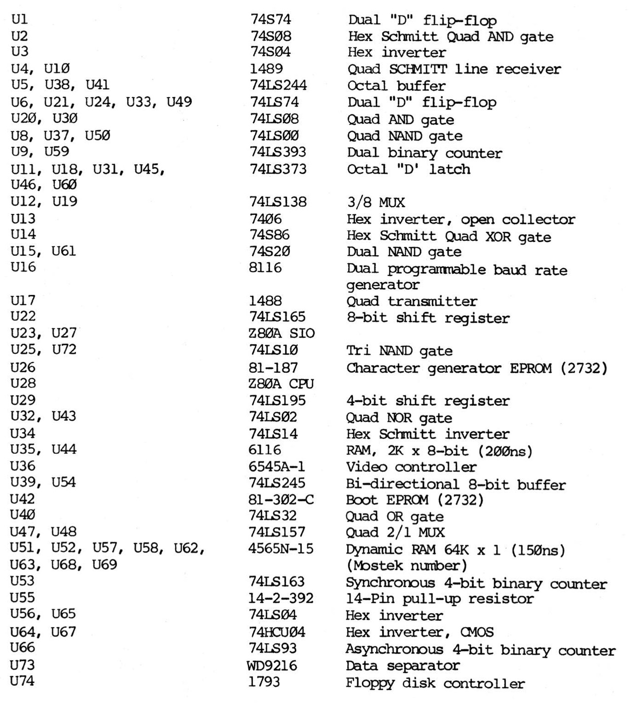
IC List
Capacitors
- C1 .. 104M . 12V ... 100.000pF, 100nF, 0,1uF
- C31 . 47uF . 16V ... 47uF
- C60 . 50K .. 1KV ... 50pF, 1.000V
- C61 . 30K .. 1KV ... 30pF, 1.000V
- C62 . 104 .. (12V) . 100.000pF, 100nF, 0,1uF
- C70 . 471K . 1KV ... 470pF, 1.000V
- C72 . 103 .. (12V) . 10.000pF, 10nF, 0,01uF
At number 5 and 7 (without volt indication) my multimeter shows 5V, i.e. 12V should be sufficient as at number 1.
But as already mentioned, my re-measurement showed that the capacitors still have their stated capacity after so many years. I would only replace it if the capacitor is visibly defective.
Even with the desoldering gun, it is difficult to remove the capacitors; I usually had to add lead solder first and only then could I desolder without problems. Very tedious.
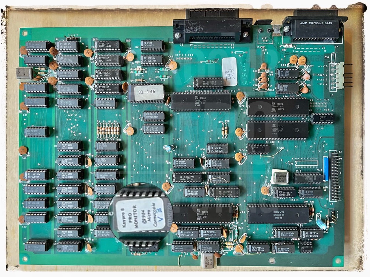
Kaypro 10('84)
The UNIVERSAL BOARD is basically installed in the Kaypro 10 ('84); with U70 (74LS157) installed.
You can immediately recognise the Kaypro 10 ('84) mainboard by the J9 hard disk connector (right middle) and the position of the RAM (lower left corner).
Revision 1
The first revision of the Kaypro 10 ('84) had no modem and no real-time clock.
Revision 2
The second revision (about 03/1985) of the Kaypro 10 ('84) had a modem and a real-time clock. [83]
On the following mainboard the R53 and C87 footprints are present and populated. The battery was removed.
The upper additional wiring is eye-catching here. This two additional wires connect the modem (secion) to the RJ45 connector on the left.
Robie (1983
The following mainboard is from a Robie '83 with two Drivetec drives.
The following UNIVERSAL BOARD is installed in my Robie '83. This board is one of the few cases with an ASSY (185). I found the ASSY sticker loose in the cabinet. Although, strictly speaking, the sticker should actually read [81-]297 for a Robie PCB!
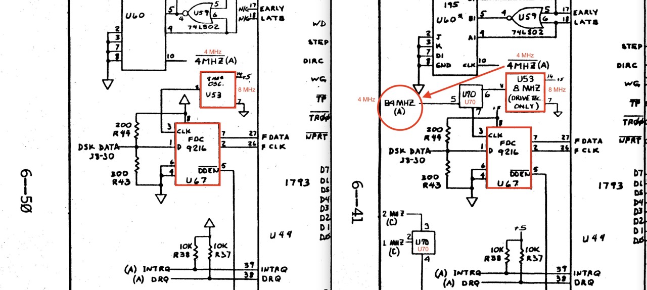
But what is important with this Robie mainboard? It has no 8 MHz clock crystal at U53 and can therefore "not" be used with Drivetec HD drives! Oops! And for this reason, my Robie does not have any HD drives installed, only DSDD.

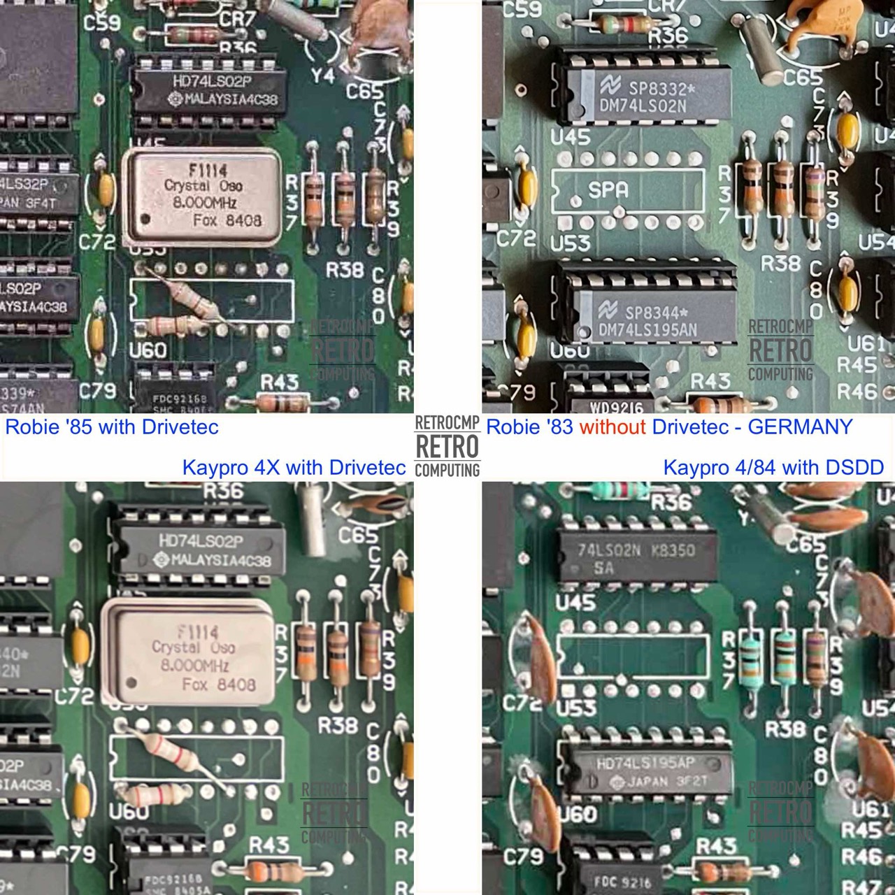
The interesting thing about the next right schematic is that it shows the 4/84, which normally has no Drivetec HD drives. But why this special representation of the U53? This is not used on a 4/84!
Normally, pin 3 at U67 (FDC9216) is the so-called REFERENCE CLOCK INPUT with 4 MHz (4/84).
Robie (1985)
The following mainboard is from a Robie '85 with two Drivetec drives.
Upgrades, Mods and Add-ons
These modifications were offered by several manufacturers. Essentially, these were Advent from Plu*Perfect, Legacy, Highland Microkit and Micro Cornucopia. In the magazine PROFILES of June 1984 - Megahertz Madness - is a summary worth reading.
Almost all modifications for the Kaypros are summarised in the following illustration. Although the company behind them is Legacy, these mods are also available from Advent and Micro Cornucopia. I'm not sure about Highland Microkit.
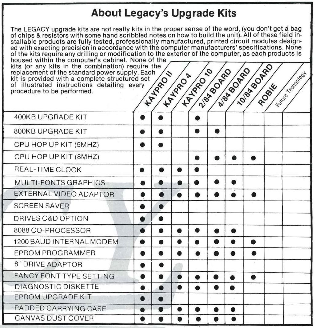
All mods available for the Kaypro II are very nicely described in Micro Cornucopia #21, December-January 1985. They are also described in the manual for "Plu*Perfect's Advent TurboROM 3.4", see A1 to B2.
But beware, the early versions of the Kaypro II mainboard are fully socketed. The modifications can be done easily. Later versions have permanently soldered ICs. Of course, modifications are also possible here, but they require considerably more effort and more manual skills. If in doubt, keep your finger off!
The modifications to increase the speed from 2.5 MHz to 4, 5 or 7 MHz applies to the Kaypro II and the Kaypro 4 ('83). Both have (nearly) the same mainboards!
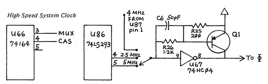
- U87 Drive Fix - Clock timing problem
- Turning a II into a 4 or into an 8 - Changing the ROM and double-sided disks
- Speeding things up - From 2,5 MHz to 4, 5 or 7 MHz
- Installing a switch to toggle between 2.5 and 5 MHz.
- Using four drives with the Micro-C PRO-8+ ROM.
In January 2022 I bought a Kaypro II (#034-644) with a Micro Cornucopia Pro-8 ROM on eBay (US). Well packed and without any damages the Kaypro arrived at my place. The modifications 1-4 were made to this Kaypro.
Kaypro II Mods
- Drive fix mod
- Clock & Pull up Circuit
- Changing the ROM from 2K to 8K
- Turning into a 4
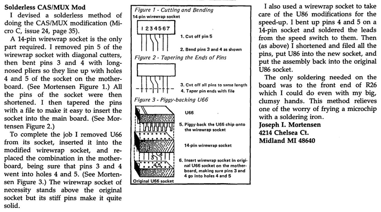
- U66 - CAS/MUX Mod
- Tuning to 4 MHz
- Tuning to 5 MHz
- Tuning to 7 MHz
- Toggle between 2,5 and 5 MHz
- Drive Select Switch
- Plus-4 Decoder
- Eight Inch Adapter Board
- Turbo Boards
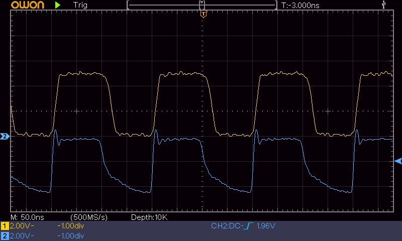
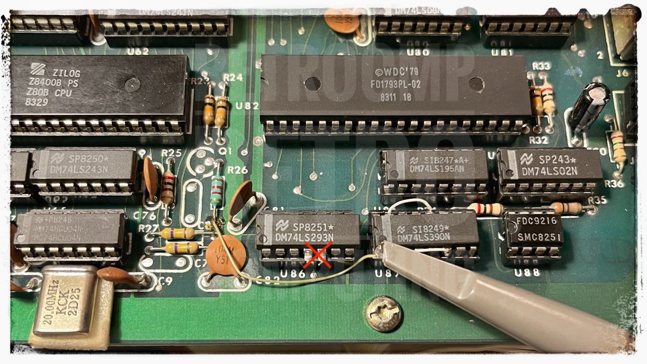
Drive Fix due to Clock Timing Problems
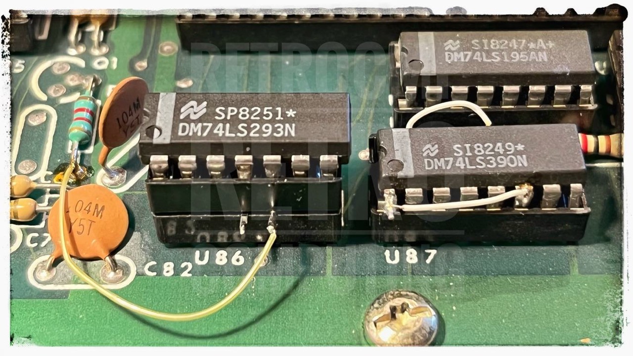
This modification is described in issue 11 of the magazine Micro Cornucopia from December 1983, page 24. You can recognize the modification immediately by two additional jumpers (thin wires) on U87.
Purpose: To insure proper timing between 1 & 4 MHZ clock as pertains to 1793 on the 81-110 mainboard.
The clock to the 1793 was slow (with respect to the processor) by about 40 nanoseconds, and that made setup and hold times critical. It turns out that with a little heat, the times got too critical. So the mod:
Remove U87 (74LS390). Cut pin 9 (or bend out), also bend out pin 1. Jumper pin 1 to pin 6. Jumper pin 12 top pin 15. Put the 74LS390 back into the socket, making sure that pin 9 and pin 1 are not making contact with anything. (If you bent out pin 9, make sure that it is not touching the resistor lead next to the socket.) Be sure that you don't get any solder down on the parts of the pins that go back into the socket.
This mod is now being done at the KayPro factory so you might take a close look around U87 for signs of jumpering. If there isn't any and you are getting drive errors, then this mod is probably just what the system ordered.

The drive fix mod is only needed for the early 81-110 mainbord. On the later 81-240 it is included!
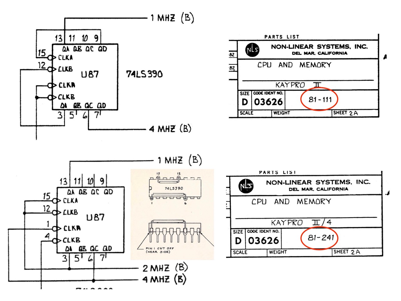
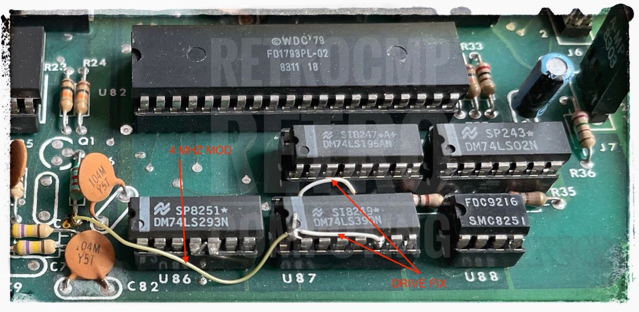
On this figure you can see the DRIVE FIX MOD on the right and the 4 MHZ MOD on the left, see below.
By the color of the connecting jumpers, you can see that the modifications come from two different hands. As you can read in #11, page 24 of the Micro-C, the DRIVE FIX was probably already done at the factory. Pin 9 is cut off on my Kaypro II (not visible in the figure).
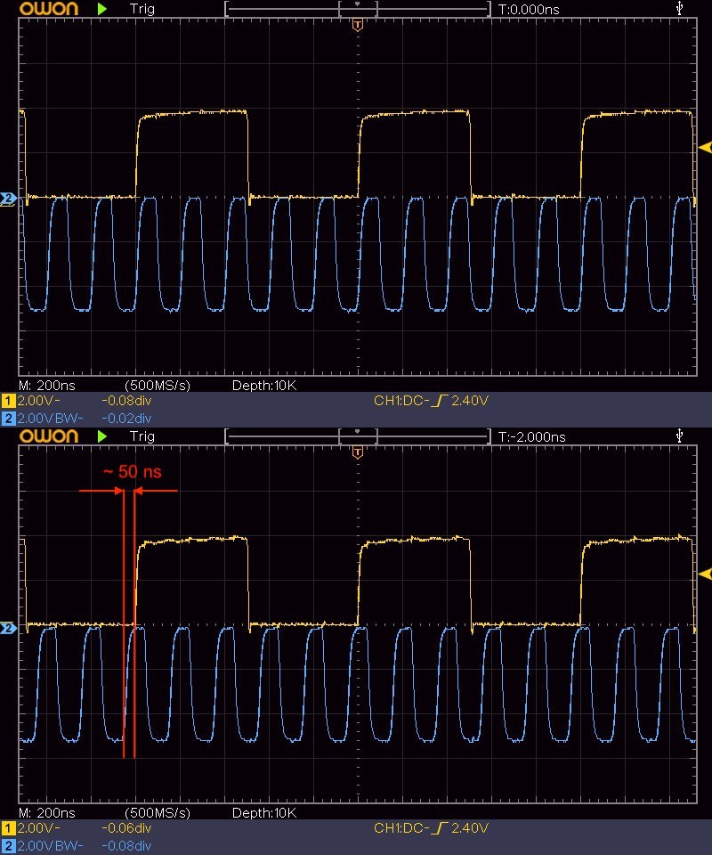
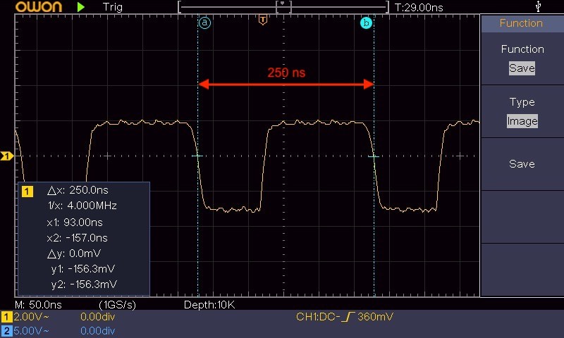
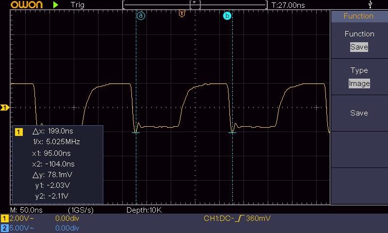
If you want to know what this mod does exactly, then take a look at the following image. I have picked up here above the modified U87 and below the original U87 with in each case the 1 MHz frequency (yellow) for the FDC and the 5 MHz frequency (blue) at the Z80B. Do you notice anything? Read the first sentence of the above quote again! ... In my case, the difference is even more than 40 ns, namely about 50 ns.
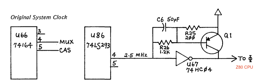
Pull up Circuit
According to issue 14 of the magazine Micro Cornucopia, October 1983 it can happen with a few Kaypro II that the Z80B gets a clock signal where the rising or fall edge of the signal takes too long. There is talk about up to 50 ns. But the Z80B expects 20 or less ns.
In this case you should add a transistor at Q1 (2N3906) and a capacitor C6 (50 pf), see C9 (50K, 1 KV) but ...
Missing Q1 and C6
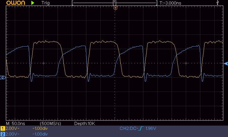
About the missing transistor and capacitor (Q1 and C6). The 74HC04 chips that Kaypro is using for U67 have been working extremely well at 5 MHz without any additional circuitry. Don't worry about the missing Q1 and C6 - they aren't needed with the 74HC04. [31]
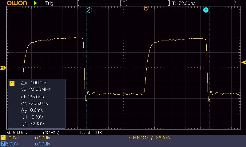
Below you can see my 5 MHz signals at U86 pin 5 (2, blue) and U63 pin 5 (1, yellow). In the second figure I have inverted the signal 2 (blue). Decisive is signal 1 (yellow) at Z80B, pin 5. I have measured here, the rising is about 15 ns and the falling is about 20 ns.
... Anyway, we speeded up both of our Kaypros. The old one (#5005) should be identical to yours [#4868]. U67 is a 74LS04 instead of a 74HC04, and Q1, the transistor pull-up is in the Z80 clock circuit, but it speeded up just as easily as the later one (number over 30,000). In fact, your old one does faster disk accesses than the newer ones. That's one rea. son why we started with the old code when we designed our PRO-MONITOR ROM. (Be sure to do the simple "drive timing fix." from issue #11 to your machine, it'll make it even more solid.) [43]
Changing the ROM size from 2K to 8K
Here is the nearly unknown mod for changing a KII 2K ROM into a 8K ROM (see appendix C, page 68). This is not just the (known) modification of a 2716 to a 2732 but to two 2732 EPROMS. The 81-110A mainboard is known to have only one EPROM although a second one would be possible. And that is exactly what was done here.
As I described above, the BigBoard I even has 4 ROM sockets. Only two were used for the 81-110A and only one of them was actually fitted with an EPROM (1st).
Turning a II into a 4 (with Micro-C Pro-8+ ROM)
++> PRO-8 MONITOR <++
==> Version 3.3 <==
At first glance, everything looks (almost) normal, but far from it. It now turns out that the Kaypro II is actually a Kaypro 4, which also supports the Pro-8 disk format with 784 KByte. And then it is not a 2.5 MHz Kaypro at all, but one with 4 MHz. But everything in order.
In the course of the further work with this Pro-8 ROM, I first asked myself what are these mods. Normally only the EPROM/ROM needs to be exchanged!
Yes, but that does not apply to this "new" Pro-8 ROM and the "old" Kaypro II motherboard. According to Micro Cornucopia you first have to turn the Kaypro II into a Kaypro 4.
At second glance, this is actually obvious because the original Kaypro II only works with single-sided disks, to name just one reason. The Kaypro 4 (from '83) and the ROM, on the other hand, are designed for two-sided floppy disks.
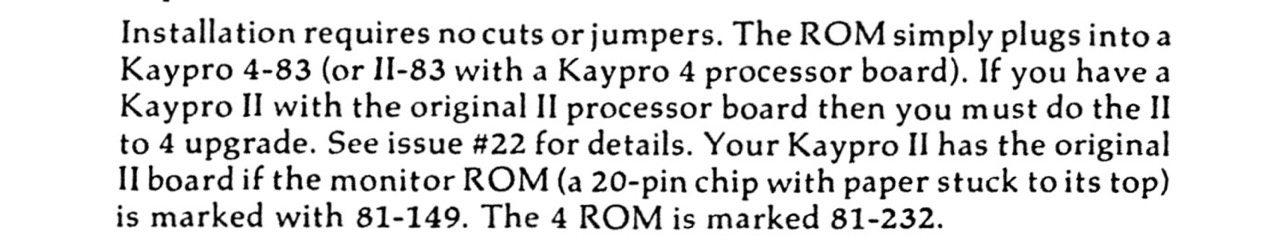
So far I have found two instructions, but they are not completely identical in content, although the result is the same, turning a Kaypro II into a 4.
(1) ... Take a look at: page 14/15 in the December 1983 issue (#15) of Micro Cornucopia: "Great Eight Kaypro" by Dana Cotant.
... and/or ...
(2) ... Take a look at: page 37-39 in "The Computer Journal" (TCJ) March/April 1993, issue #60: "Mr. Kaypro: Today's Project" by Charles B. Stafford. There is also a good illustration on page 39. My Kaypro II mainboard has basically the mods according to TCJ. You will also find a good illustation in the Micro Cornucopia (#24), June-July 1985 on page 35.
Reference (2): The modifications described here refer basically to the CPU SECTION: U47/U59, U60, U73/U72 and U73/J6; where U72 and J6 strictly refer to the I/O SECTION. These four single mods are required to add a select circuit to pick up the extra 2 KB in the larger ROM, to connect line A11 to pin 21 of the larger ROM and to add the "select line" for the floppy drive (SIDE SELECT).
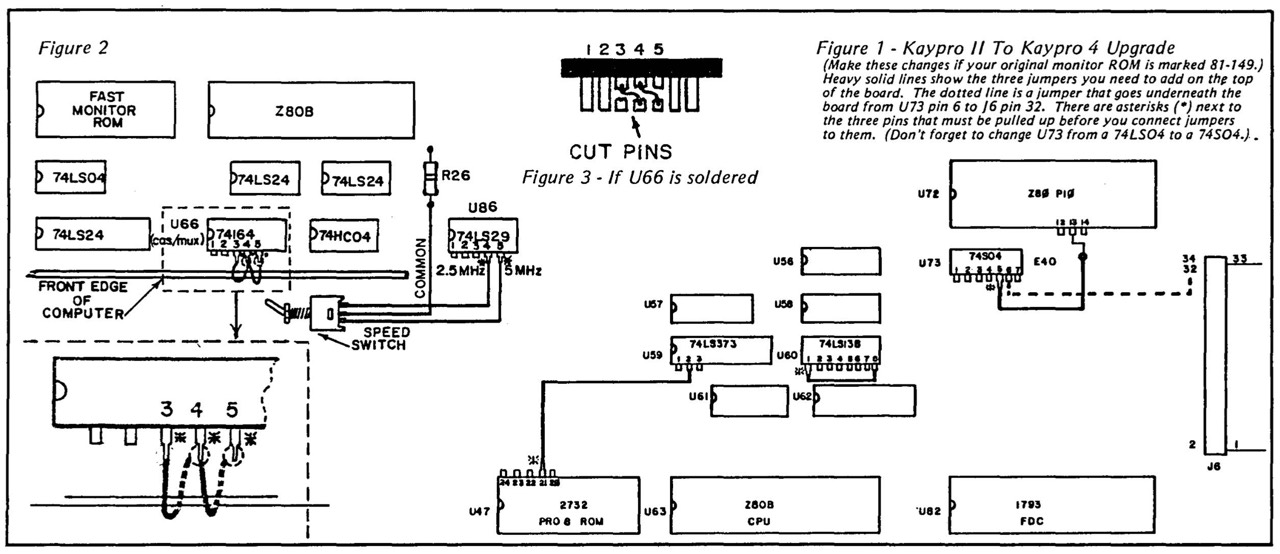
Figure 1 shows the KII to K4 mod. Figure 2 & 3 show the CAS-MUX mod for the speed modification, see also below: U66 ...
The modification at U60 is also described in a letter to the editor [by Greg DeHoogh] in Micro Cornucopia #18 on page 3, June 1984.
Dear Editor, I modified my Kaypro II to access all 4k of a 2732A, in anticipation of bigger and greater things. I did the chip select decoding a bit different from the method described in your December issue. I simply bent up pin 1 of U60 and jumpered it to pin 8 (ground). This changes U60 to a 1-of-4 decoder using outputs 0, 2, 4, and 6 which decode on 4k boundaries. The CRTCE isn't affected since outputs 6 and 7 are ORed together anyway. This method eliminates the need to add in an extra gate and the accompanying jumpers.
--Greg DeHoogh 15711 Williams St. #172 Tustin CA 92680
Editor's note:
Thanks a lot Greg. Dana and I hadn't even thought about doing it this way. We tried it and it works fine! This is a great device select shortcut for all of you who are upgrading a Kaypro II to a 4. [40]
And here is another optimization.
Dear Editor:
After hours of studying issue #15, "Great Eight Kaypro," and issue #18, Greg DeHoogh's letter to the editor, I started to make the modifications to prepare my Kaypro II for the 2732A monitor ROM chip and double-sided drives. Greg DeHoogh's suggestion of bending pin 1 of U60 and jumpering it to pin 8 seems a lot easier than hooking up to the additional gate in U80.
However, could you please clarify one thing. If I use this alternate method of selecting the second half of the 2732A, does the ALL line on the 2732 ROM (pin 21, U47) still have to be jumpered to U59, pin 2? Or, is this step also bypassed (DeHoogh says, "This method eliminates the need to add in an extra gate and the accompanying jumpers.")?
I've previously followed your suggestion of using a 24-pin dip socket. On certain jumper schemes, I use 2 dip sockets stacked one-upon-the-other, with the original IC installed on top of this little "hi-rise." While this method may take longer to put together and test out (before plugging in), it at least prevents irrevocable damage to the main circuit board.
With this in mind, my solution for the floppy side select was to bend out pin 5 (U73) on a dip socket, solder wire-wrap wire to this bent out pin, and run the wire-wrap wire to the PIO (U72). After carefully removing the 40-pin PIO, the insulated stripped end of the wire was inserted into the U72, pin 13 socket, after which the PIO was reinserted.
Wire-wrap wire was carefully wrapped and soldered to pin 6 of the IC socket. After pulling out the dip header for the floppy drives, the other end of this wire was wrapped to pin 32 on J6, and the header reinserted. This dip socket was inserted into U73 with the new IC, a 74504, inserted instead, or the original 74LS04.
This method eliminated removing the board from its mounts, and allowed the modifications to be easily removed.
--Brian Tanaka, 3479 Pinao Place, Honolulu HI 96822
Editor's note:
Even with DeHoogh's modification you still have to jumper pin 21 of the monitor ROM to U59 pin 2. Also, good suggestion on the mods. Be sure to use high-reliability sockets. The Augat brand sockets have been quite good. [36]
I have tested the Pro-8 ROM with the following drives with success so far: all double-sided, quad-density, 80 tracks, 300 rpm, 250 kbit/s.
- Panasonic, JU-475-2EAF: ... TM, DS2, DS, RDY, SP, DA, MM
- Panasonic, JU-475-5 AKO: .. TM, DS2, DA, BX
- Mitsubishi M4853: ......... DS1, HC, MM
- TEAC FD-55GFR-193-U: ...... DS1, RY, I, LG
Do not be confused by DS1 or DS2. This depends on the respective numbering; DS0-DS3 or DS1-DS4. You have to set the jumper to the 1st drive, if you want drive A: or to the 2nd drive, if you want drive B: !
The special thing about the Panasonic and TEAC drives is that you can set the speed 360 or 300 RPM directly with a jumper. These are real dual-speed drives! Many other "dual" drives 1.2MB/360KB on the other hand rotate with constant 360 RPM and therefore write/read the data (for 360KB) with 300 kbit/s instead of usual with 250 kbit/s.
For this reason, you can use these regular "1.2MB" drives as true 720K/1M drives. Of course, you can also use the common Tandon TM-100-4 full-height drives. Watch out! Use double-density (DD) and not high-density (HD) floppy disks!
If you have a TEAC FD-55GFV or -GFR drive, take a look here: Changing 360 RPM to 300 RPM.

A Kaypro IIX never officially existed, of course. What is meant here is a Kaypro II upgraded to a Kaypro 4 with a Pro-8 or comparable ROM. In other words, this Kaypro IIX can read 784 (800) KByte floppy disks.
Micro Cornucopia's Pro-8 ROM can read all three Kaypro disk formats (191K, 380K, 784K) with the Mitsubishi M4853, but ... Never write to a floppy disk with a 96 tpi drive, if it was previously formatted with a 48 tpi drive and also already written! The disk will most likely not be readable in a 48 tpi drive afterwards! Why, you can read it here.
In principle, you could also take the Advent TurboRom '83 from Plu*Perfect if you want to turn a Kaypro II into a Kaypro 4. But! This ROM has a very decisive disadvantage. For quad-density drives (784K) you need the so-called decoder board. I just tested it. 384K works, but 784K does not!
So with the Kaypro II and 4 ('83), you'd better go with Micro Cornucopia's Pro-8 ROM.
U66 - CAS-MUX Modification
This mod is needed in conjunction with the following 4 or 5 MHz speed mod. The description comes from a user letter to Micro Cornucopia (issue 27, page 84 from December-January 1986). Herewith the modification should be possible without soldering. Sounds good.
Tuning to 4 MHz
But there are three more modifications on my Kaypro II motherboard. These are located at U66, U86 and R26/U87. These three mods also belong to the CPU SECTION.
At first I didn't know what to do with this. But while browsing through the other TCJs, I found what I was looking for in issue #61. It is another ingenious modification: Kaypro 2.5 MHz to 5 MHz. I am speechless!
### Update 03.02.2022: I'm afraid I have to correct myself a little. With the 5 MHz I was not bad at all, but it is "only" 4 MHz. I noticed my small mistake, because I saw in the issue 12 of the Micro Cornucopia (June 1983) on page 25, that with me the PIN's 4 and 5 with U86 (74LS293) are bent up and thus out of function. On PIN 4 2.5 MHz and on PIN 5 5 MHz are present. And exactly this PIN 5 is normally used for the 5 MHz mod! But I use PIN 1/6 on U87 (74LS390) and exactly here are 4 MHz. Riddle solved. ###
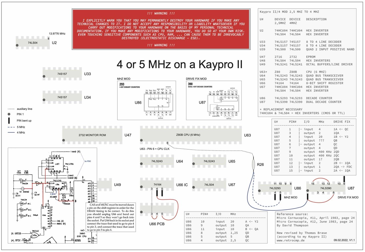
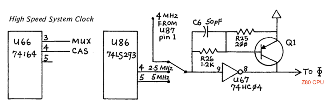
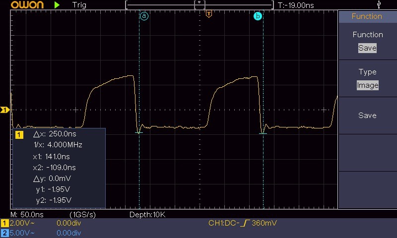
Calculated on foot: 5 x 50 ns = 250 ns = 0.250 ms. 1 / 0.250 = 4 MHz. Actually quite simple.
Tuning to 5 MHz
The 4 MHz and 5 MHz mods for the Kaypro II or 4 ('83) are described in issue 12 of the Micro Cornucopia (June 1983) and also in issue 61 of "The Computer Journal".
And here I changed the 4 MHz mod to the 5 MHz mod on the fly. Just remove the jumper from U87 pin 1 and solder it back to pin 5 of U86. That was it.
In my Kaypro II (#034-126) I found the following variant of the U86 mod. Below the mainboard PIN 4 (2,5 MHz) leads directly to R26. Simply ingenious.

Furthermore I exchanged U33 and U34, the slow 74157/74LS157 against the faster 74F157. Whether this exchange is actually already necessary at 5 MHz, I cannot say. At least it is recommended for the 7 MHz mod.
Today's result: My Kaypro II with 5.0 MHz is now "faster" than the first IBM PC or XT. This one only had 4.77 MHz.
Tuning to 7 MHz
You can also tune up your Kaypro II or 4 ('83) to 7 MHz. This mod is described in the Micro Cornucopia, issue 33, page 56 following.
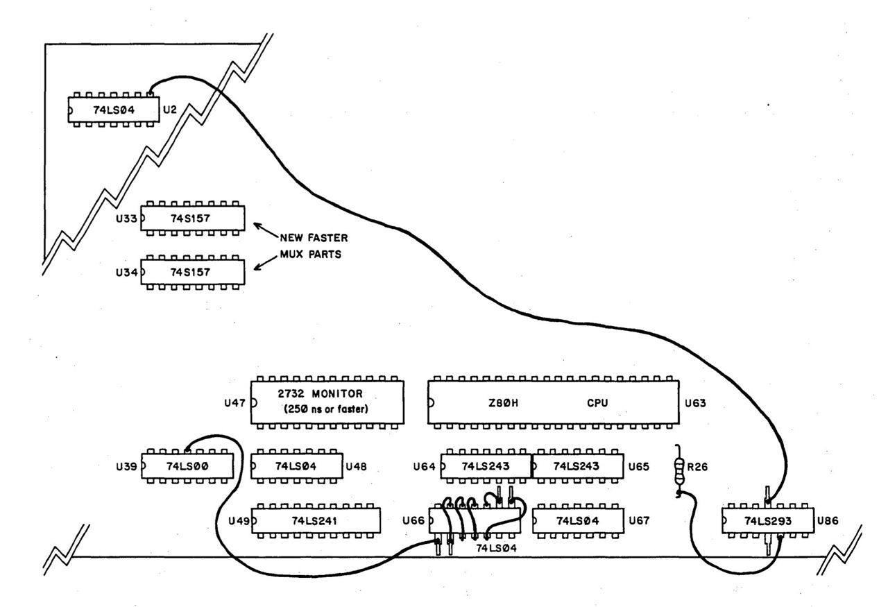
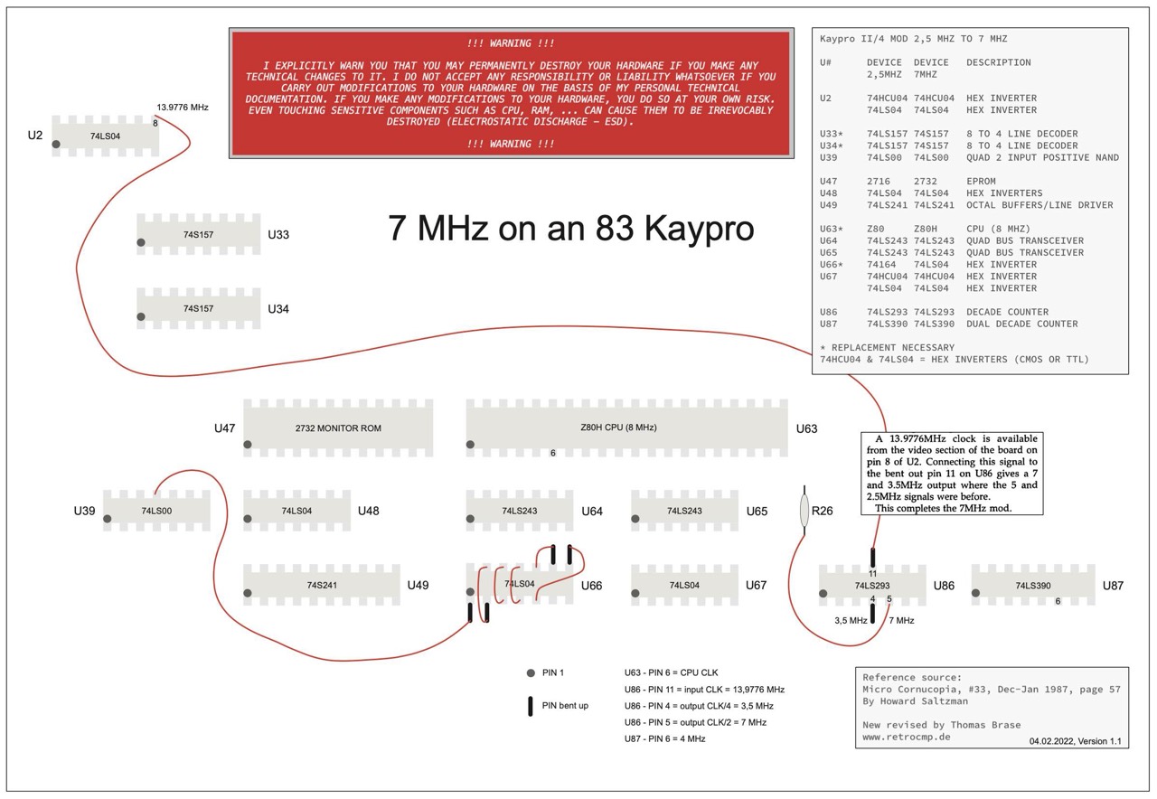
I have not yet performed the modification to 7 MHz. I actually want to do this on a completely new/different motherboard.
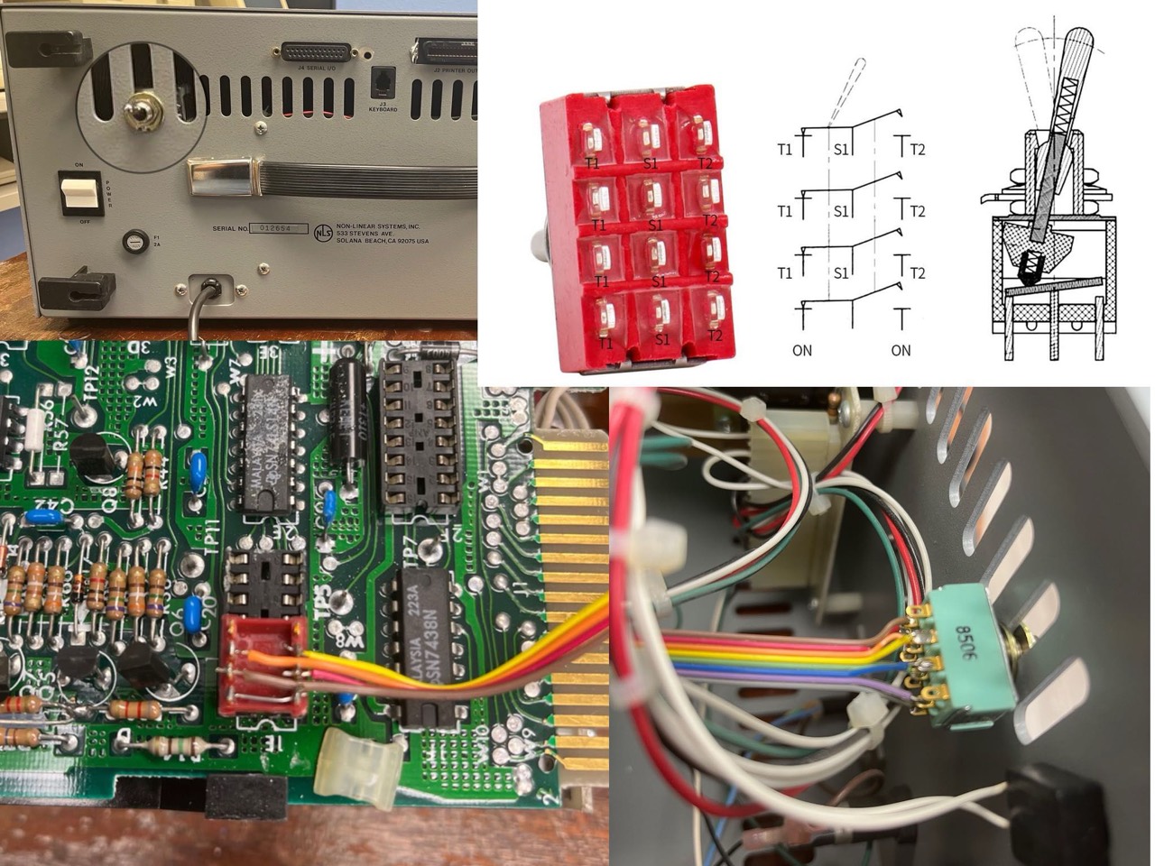
Toggle between 2,5 or 5 MHz

Why this switch? It can happen that one or the other software only works correctly with 2.5 MHz. So I can then simply switch back.
The builder of the tripple speed mod below was just brilliant. By simply plugging it in, you can switch between 5 and 4 MHz. Much better than the construction in the Micro Cornucopia!
This flexibility is ingenious but not really necessary. If you have 5 MHz, then you don't need the 4 MHz. But this mod shows the craftsmanship and that it is perfectly thought out.

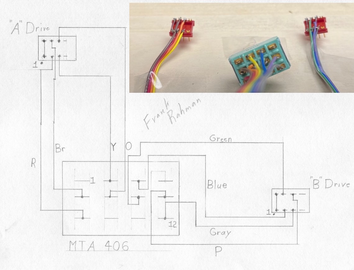
Drive Select Switch
If you want to toggle between drive A-B and B-A then make a DRIVE SELECT switch mod; simple but effective. This makes only sense if you have different drives!
Frank Rahman also has a wonderful Kaypro collection!
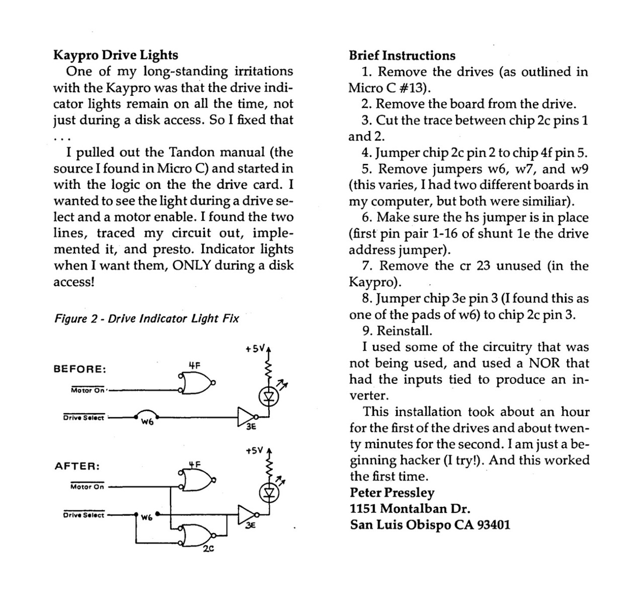
Drive Indicator Lights
Only valid for the full-hight Tandon drives. I have not tested this modification. Use it at your own risk!
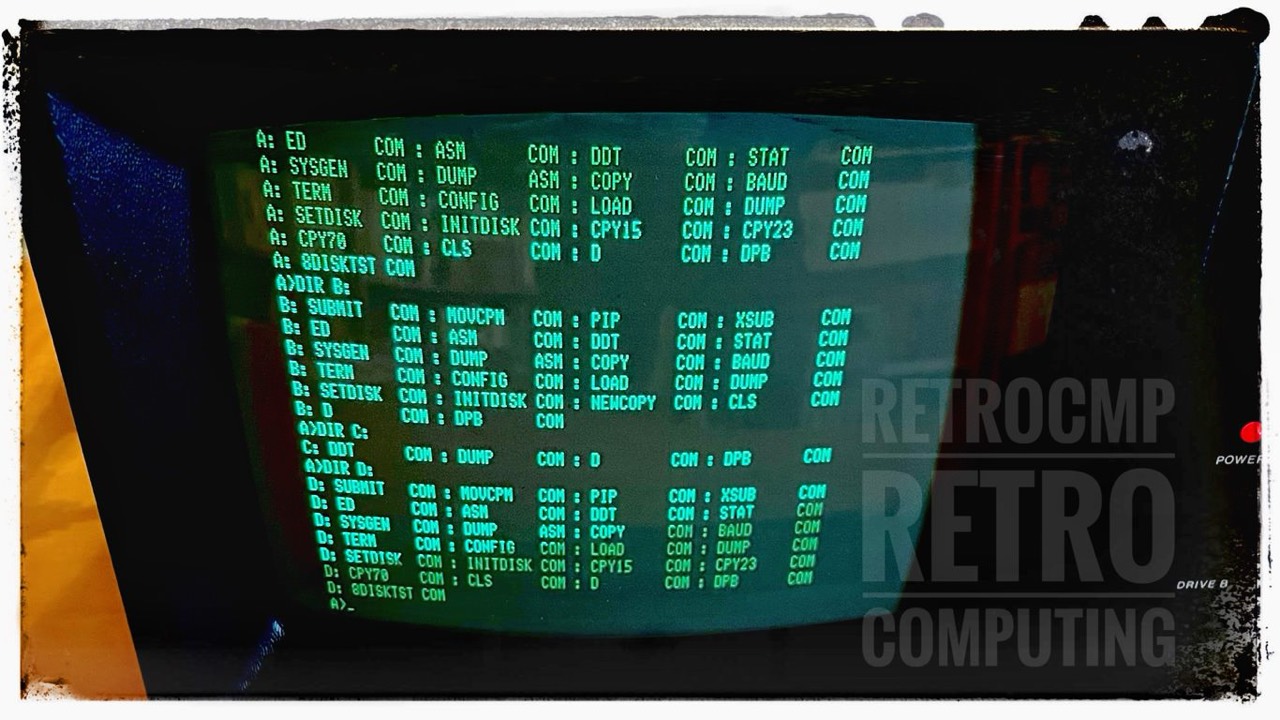
Using Four Floppy Disk Drives
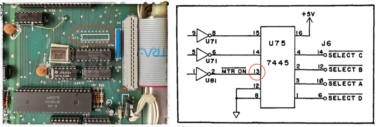
Plus-4 Decoder by Micro Cornucopia
Mainboard Mod 1
Detailed instructions for this mod can be found twice in the Micro Cornucopia magazine. Both mods are almost identical. I have not tested them because I do not want to change my mainbord! I use the decoder board below.
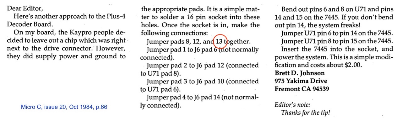
Mainboard Mod 2
The difference (red circle) is in pad 13 on U75.
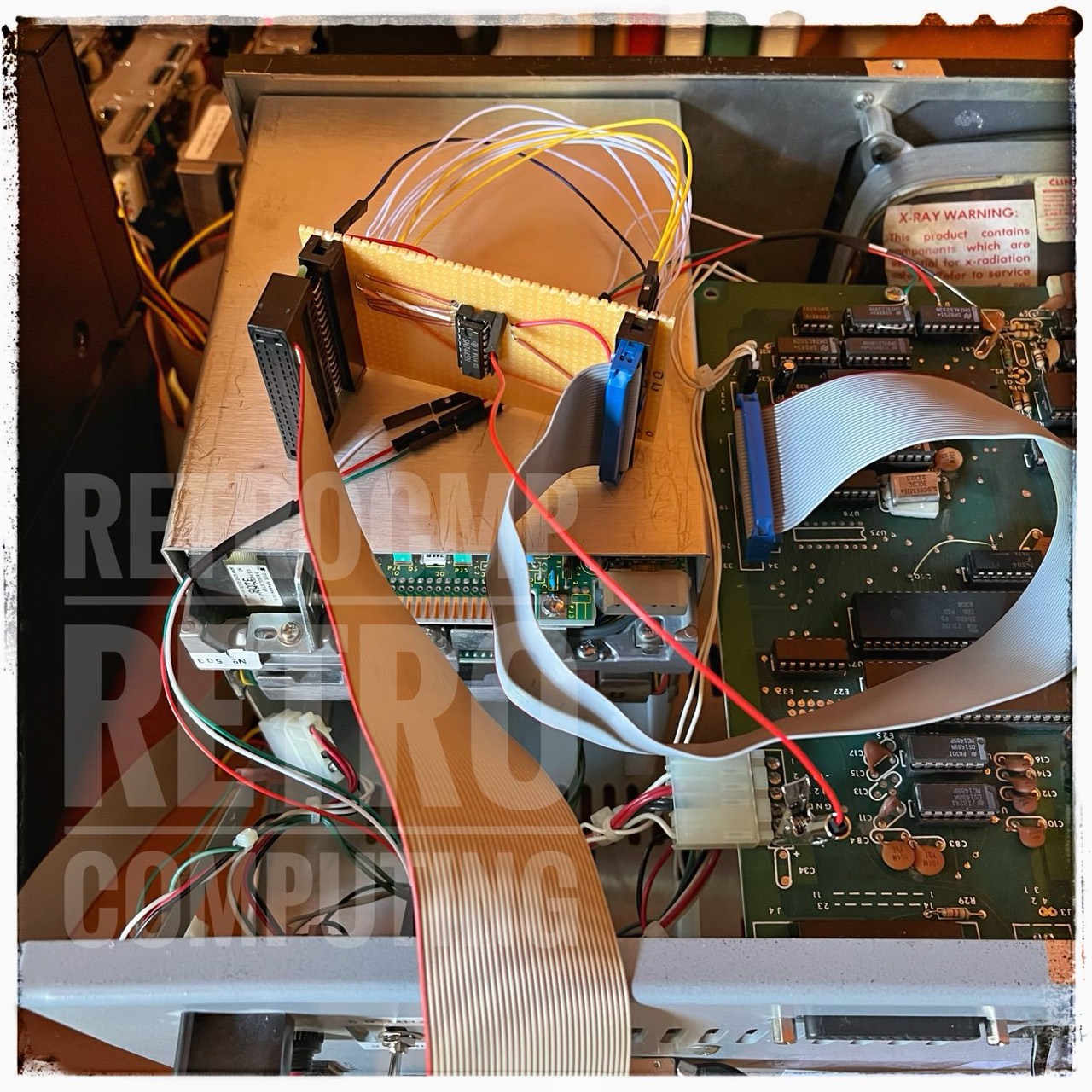
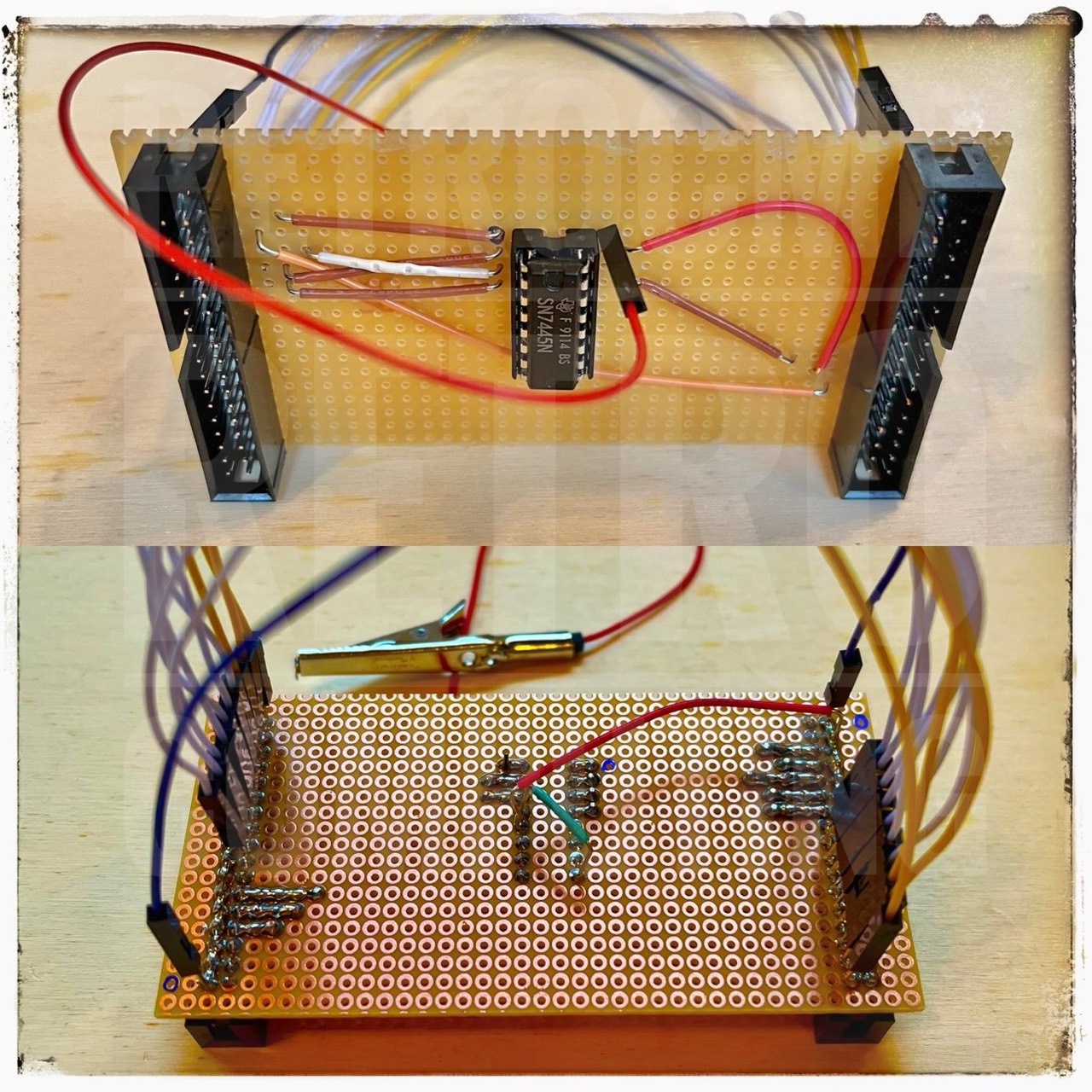
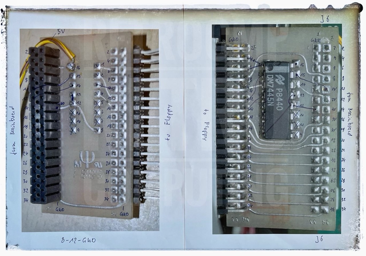
Decoder Board - Prototype
If you do not want to change your mainboard, then you have to make a small additional decoder board yourself. You can download the necessary Gerber files at the end of this page.
... Four-drive decoder. You can buy Micro C's Plus-4 Decoder Board or you can buy a 7445 chip and a 16-pin socket and make your own. [33]
With this nifty little plug-in board, your Pro-8+ ROM can access up to four 5.25" drives. You just plug a four-drive 34-pin cable into this board and you can add up to two additional drives.
Now you can run any mix of 191K, 390K, and 784K drives as drives A, B, C, and D. You can run your original drives as A and B then add 380K or 784K drives outboard as C and D. You can even run four half-wides inside your original Kaypro!
Various Micro Cornucopia magazines
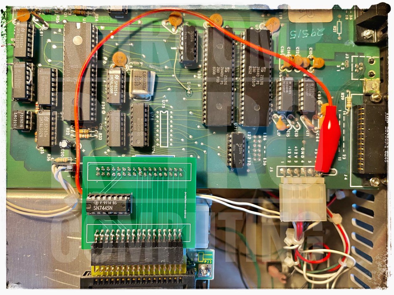
Since the Plus-4 decoder board can no longer be found/purchased today, you have to do the mod yourself. On the following pictures you can see my prototype. Not pretty, but it works!
I disconnected the two existing built-in drives for the test and connected four external drives to a approx. 2.5 m (i.e. 8.2 ft) daisy chain cable. Later I will equip this Kaypro II with a total of four internal drives. But first I have to completely redesign the decoder board with KiCad. Let's see when I have time.
I forgot to mention that this Kaypro II already has various mods. Among others, it runs at 2.5 or 5 MHz and has a Micro Cornucopia PRO-8+ ROM.

Decoder Board - KiCAD PCB
Here is my template; who wants to can try it! I have to admit, at the beginning I wasn't sure if it would really work. But you have to have some confidence.
The first board designed with KiCad is ordered on 20.04.2022 at JLCPCB. Today's (23.04.2022) e-mail: "Your JLCPCB Order Is On Its Way To You".
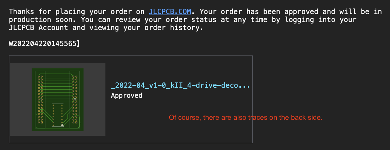
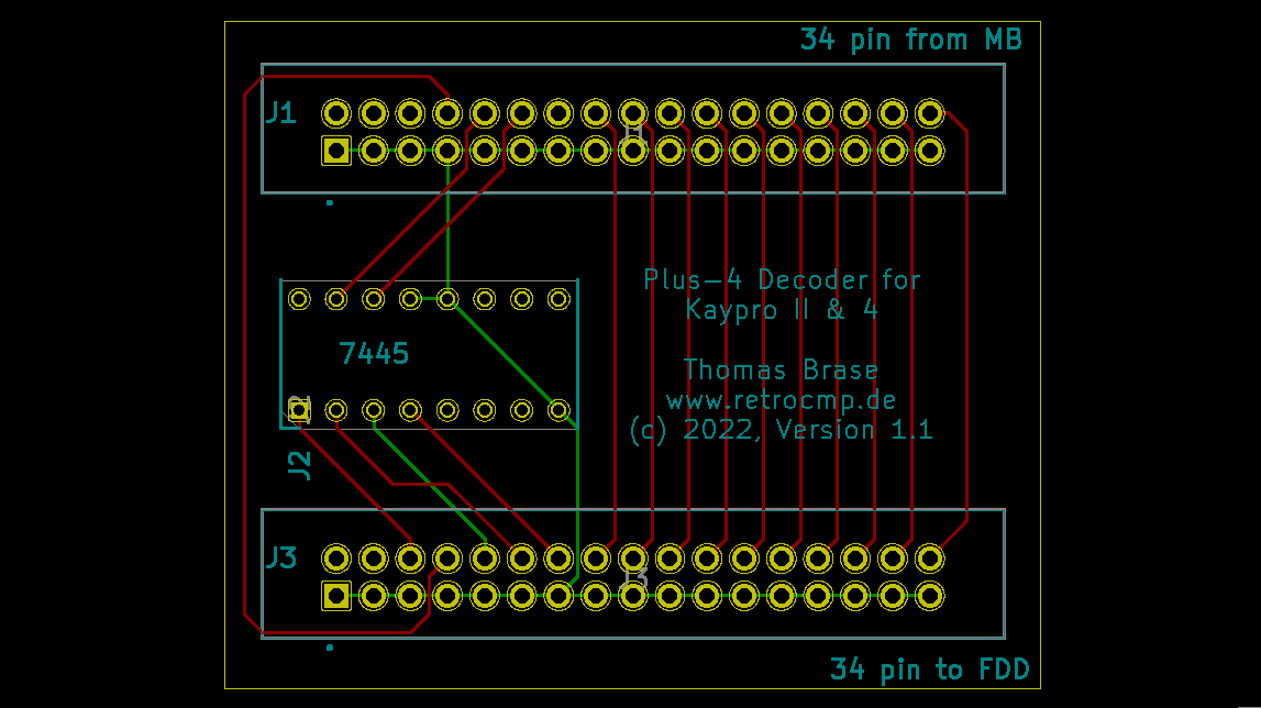
There is absolutely no need to make any changes to the mainboard, contrary to the description in Micro Cornucopia [54]. You can download my Gerber files for version 1.1, see below.
This decoder board actually only makes sense with the Kaypro II with two full-height disk drives. Only here you have space for four half-height drives.
Important notes:
(1) This PLUS4 board I constructed based on the pictures above works fine in my modified Kaypro II. The decoder should also work in the Kaypro 4 ('83), because both boards are nearly the same.
(2) It does NOT work with the Kaypro 10 because the (floppy) DRIVE SELECT B signal is used by the system to access the hard disk.
(2) You must use a 63K CP/M. You possibly have to reconfigure your CP/M with MOVCPM and SYSGEN.

Personality Decoder by Advent
In addition to the Micro C Plus-4 decoder described above, there is also a comparable one from Advent, the Personality Decoder. A replica is described in the magazine "The Computer Journal - TCJ", issues 66 and 69. However, this replica is more complicated than the Plus-4 decoder. But read it yourself.
Eight Inch (8") Adapter Board
The following advertisement is from the Micro Cornucopia of December 1985, but so far I have not seen any Kaypro with this adapter board, nor have I found any further information about it on the Internet.
OK, you asked for it: the 8 inch adapter board for the Kaypro. Now you can have:
1. 4 drives
2. Up to 1.3 meg of storage per disk.
3. Access to SIGM and CPMug software.
4. Super fast data access.
The circuit board, ROM, and disk in this package will let your Kaypro run up to four drives. A and B have to be 5" drives, C and D can be either 8" or 5". The eight inch drives can read and write single density, double density, or double-sided double density. Plus, if you have an 84 2 or 4 you get all the Pro-884 MAX features.
The 8" adapter board plugs right in (no cuts, jumpers, or soldering - unless you have a Kaypro II, then you have to do a II to 4 upgrade.) You supply the drives, cabinet, and power.
8" Adapter Board ............... $190.00 [34]
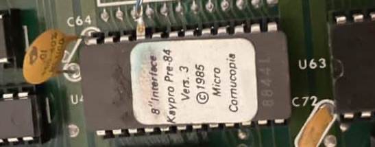
Update 27.07.2022: And here is something very rare and special. You need this ROM for the Micro Cornucopia 8" adapter board.
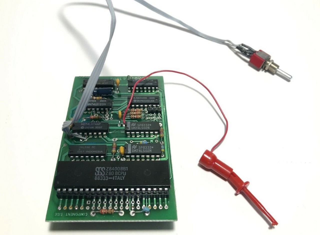
Turbo Board
As you can read above, the turbo modification from 2.5 to 4 or 5 MHz is actually quite simple - for the skilled hobbyist. For the normal computer user this modification is of course a no-go. Here a very simple solution had to be found.
Therefore, the so-called turbo boards were developed. Here are two examples. Both with Z80B CPU (max. 6 MHz).

Kaypro 10 ('83)
Changing the EPROM from 4K to 8K
You can read about this modification in detail on this page. You will need this mod if you want to use, for example, Plu*Perfect's Advent 8K TurboROM 3.4 in a Kaypro 10 ('83).
Hardware option: 5 MHz Card
Acording to Practical Computing, 04/1984, page 69 there was also hardware option: a 5 MHz card.
UNIVERSAL BOARDs
Upgrading the Real Time Clock (RTC) Parts
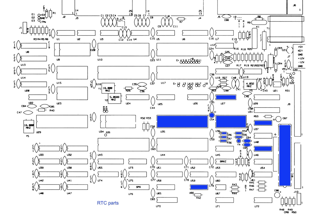
In this article you will find all further information and a parts list.
Upgrading the Hard Disk Interface Parts
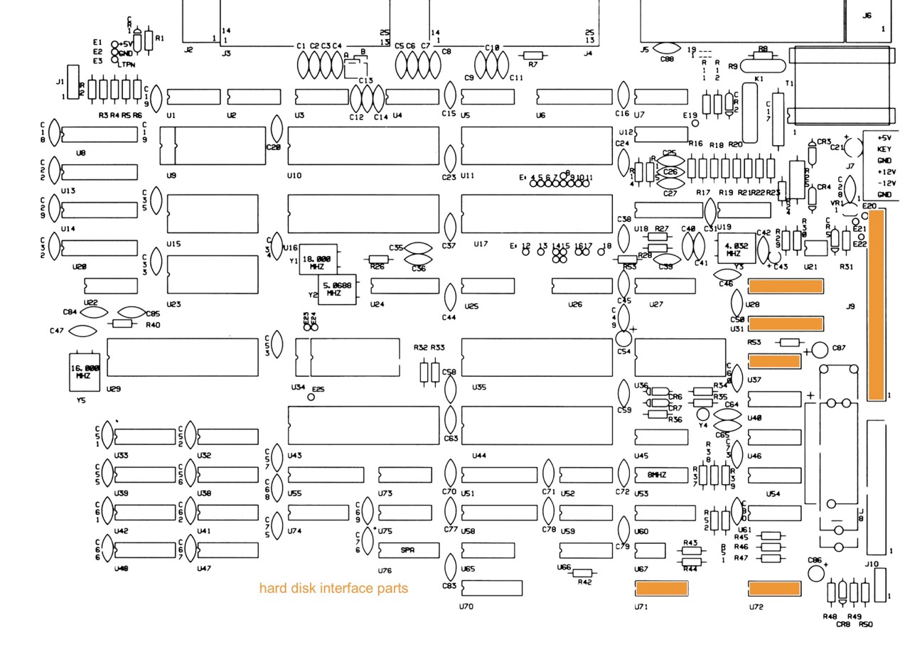
In this article you will find all further information and a parts list.
Other
SWP CO-POWER-88 Board
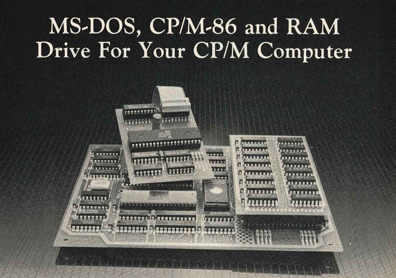
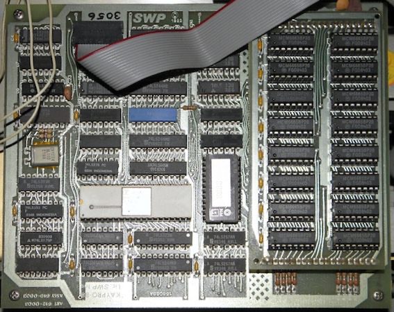
The CO-POWER board is first mentioned in Micro Cornucopia magazine in issue 15 of December 1983 on page 30. Special versions of the Kaypro II and 4 could be purchased with this board for an additional $400.
CO-POWER-88 is a powerful 16-bit, 8088 co-processor that upgrades your Z-80, CP/M computer. It runs both MS-DOS and CP/M-86, making it MS-DOS, IBM-PC compatible, and can be used as a RAM drive for CP/M. The CO-POWER-88 is now a factory option from your local Kaypro, Morrow, Zorba and Actrix dealer, or if you already own a CP/M Computer, you may order a retrofit kit by mail directly from SWP. You may order a retrofit kit by mail directly from SWP for the following computers: Kaypro II, 4, 4/84, 10; Xerox 820 II; Bigboard; ATR8000; Zorba; Osborne.
It runs at a fast 5.3 MHz and is available with your choice of 128k or 256k RAM. Using a maximum of just 750 mils at +5 volts, the CO-POWER-88 gets its power from your computer's power supply. And CO-POWER-88 is lightweight: the 256k weighs less than one pound!
When you order your CO-POWER-88, you'll receive two circuit boards: the Z80 adaptor board and the main processor board. You'll receive a complete owner's manual and easy-to-follow installation instructions.
MS-DOS is included with your CO-POWER-88. Except for machine depend programs, that means that CO-POWER-88 is IBM compatible. CP/M-86 is available as an option.
Once MS-DOS is booted, your computer can actually read and write IBM-PC disks, and the MS-DOS format program can format in the IBM-PC disk format. [28]
A short review can be read in the BYTE of December 1983 on page 338. Unfortunately, the picture there is only very small. But it shows both, the main processor board and the adapter board.
SWP's CO-POWER-88 board is/was available for the Kaypro II, 4, 4/84 and 10. [26]
KAYPRO 10
Steve McMahon's review of the Kaypro 10 ([BYTE 1984], May, page 206) neglected to mention an important feature available for this machine, the CO-POWER-88 board by SWP Microcomputer Products Inc., of Arlington, Texas. Available as a factory option or directly from SWP, the CO-POWER-88 upgrades the Kaypro so it can run MS-DOS and CP/M-86.
FRED L. HELMS, SWP MICROCOMPUTER PRODUCTS, Arlington, TX [27]
But watch out! According to the statements in the SWP Kaypro manual, the boards are specially adapted to the respective model. [59]
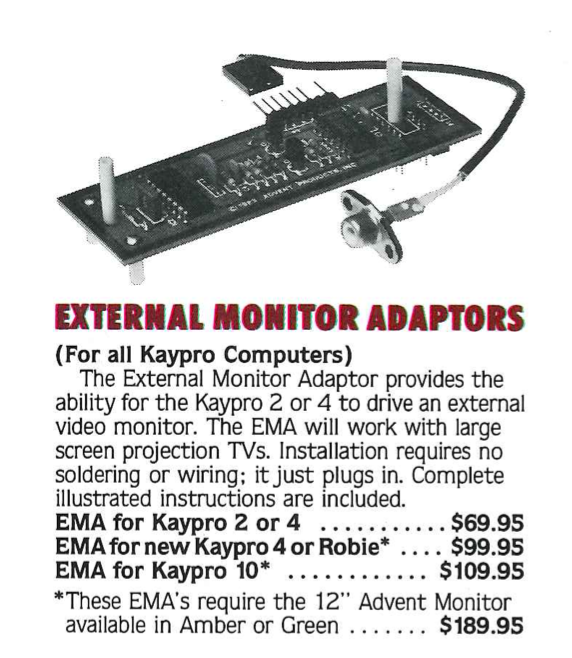
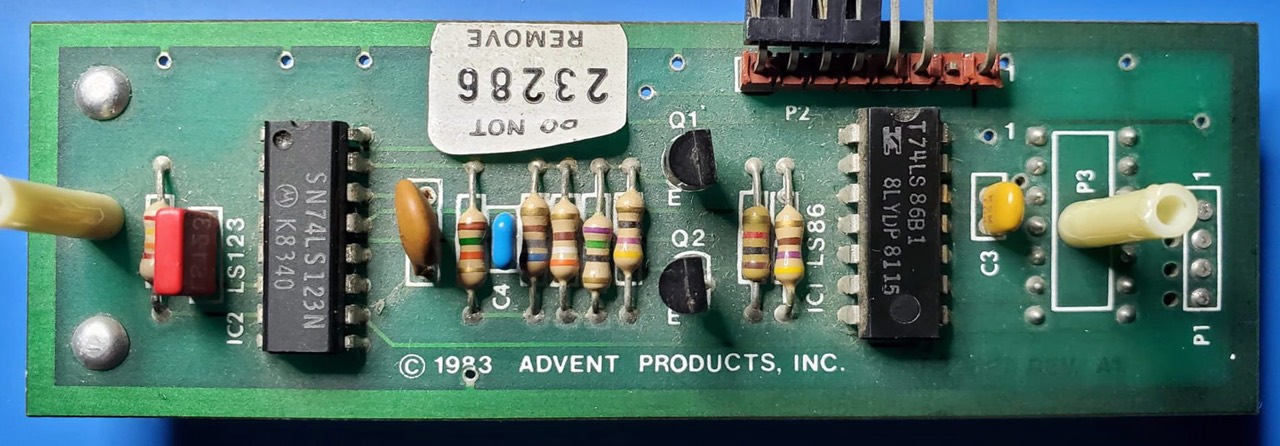
Monitor Adaptors for the Kaypro
KayNet - Local Area Network for the Kaypro
Kaypro and Centram Systems have unveiled KayNet, a local area option for the Kaypro family of mobile micros. ... The networking software, called OPSnet, supports almost all conventional CP/M 2.2 programs without modification. [63]
A TRULY AFFORDABLE NETWORK
The cost-effective design of the KAYPRO computers permits KayNet to be one of the few truly affordable local area networks. Any KAYPRO may be simply converted to a KayNet station at a minimal incremental cost. Fitting easily within existing office environments, KayNet is less expensive to install and maintain than traditional multiuser mini computer systems. This makes the KayNet approach to networking comfortably within reach of any company's budget.
Each computer in the KAYPRO line is a versatile, selfcontained unit providing more than enough power to handle the day-to-day business challenges. However, as the demands of the modern office have expanded to include greater access to this kind of power and information, the need for a local area network has become apparent. In response, KAYPRO computers, thus allowing the sharing of resources and information. A practical system may utilize up to 20 KAYPRO II, 4, or 10 computers in virtually any combination, while as many as 60 stations may be feasible. [61]
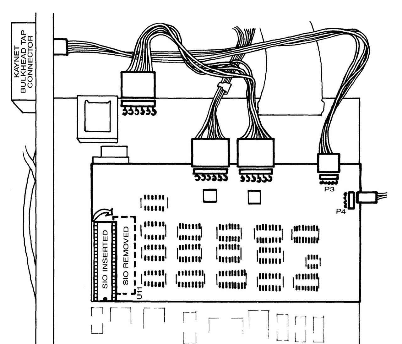
The following picture shows the KayNet ULCnet connector adapter from Centram Systems.
ULCnet is the abbreviation for Ultra-Low-Cost Network. If you want to know more about this, please read the article in the BYTE of October 1981, page 50.
Gotek / FlashFloppy
Of course, it's a bit sacrilegious to disfigure a 40-year-old computer with a plastic USB drive, but ...
In my Robie, for example, I (first) installed two new wonderful 800K drives. So far, everything is actually quite good. But how do I get files from the Robie onto my Kaypro 10, which only has a 400K drive? Standard answer: with Kermit. Yes, Kermit works of course always and also very well, sometimes a bit slow. The longer answer is: with a 400K floppy disk. But this is where the problems start and they can be very annoying. With DOS there is also this problem and that is when writing 360K floppy disks in a 1.2M dual speed drive.
Skillfully you can circumvent this problem with a Gotek drive and FlashFloppy as operating system. FlashFloppy can read and write all three Kaypro formats. Just change the Kaypro and the USB stick and you're done.
I forgot to mention that my Robie (now) has a Micro Cornucopia Pro-884 Max ROM. This can read and write all three Kaypro formats (200K, 400K and 800K) with a DS QD floppy disk drive (Panasonic JU-475-5: 2 sided, 96 tpi, 80 tracks).
ROM
This content has changed to: Kaypro ROM, EPROM
Hard Disk Controller
The Kaypro 10 ('83) uses the WD1002-HDO (HDO = Hard Disk Only) controller; this is a MFM and not a SASI controller. The WD1002-HDO is a depopulated version of the WD1002-05. The floppy drive is connected directly to the mainboard (J8) of the Kaypro 10 ('83). The FD-1793 IC (U74) is used as floppy disk controller on the mainboard. In my case this is a SYP1793-002 from the SYNERTEK company.
The WD1002-HDO is a depopulated version of the WD1002-05. All Floppy drive control and associated circuitry has been deleted from the board, providing a Winchester Drive Controller board that will drive up to three 5 1/4" Winchester disk drives.
WD1002-05/HDO Winchester/Floppy Disk Controller OEM Manual

Important note for ASSY 61-031050: It is essential to use a plastic screw for fixing at the bottom right hole (red arrow). If you do not do this, you might short-circuit the resistor R57 with the cabinet! If you mount the PCB, this hole is located on the upper left!
If you need to change the hard disk, it is best to use a Seagate ST225. The connection (MFM) is made via the two marked connectors. Your drive must be „jumpered“ as DRIVE 1 (J2). The hard disk must also be jumpered as the 2nd drive.
You will immediately notice if the drive has been selected incorrectly because the FORMAT command cannot find the drive.
In the Kaypro, as far as I know, the ASSY (assembly no.) 61-031050 is used. Besides that I found another controller in the internet with the number 61-031093. This ASSY appears both as WD1002-HDO and as WD1002A-HDO! I have two eBay sale pictures in my collection.
I bought the following controller months ago for very little money on eBay (2 pieces for 30 EUR). If I remember the offer, the controller was installed in a „Rohde & Schwarz PCA 5“; but I'm not quite sure.
My further research on the Internet showed that the WD1002-HDO was also used in the „NCR DECISION MATE V“.
### Update 05.12.2021: Today I exchanged both PCBs and did not make any further changes. And lo and behold, they are compatible. The hard disk works perfectly. ###
Interface Board
According to Mirco C [12] the interface board - mounted on the winchester housing under the mainbord - can be changed so the Kaypro 10 can use the Xebec (SASI) or the Western Digital (ST-506) hard disk controller. However, I am only aware of the Western Digital controller WD1002-HDO so far, see above.
This statement in the Micro C is of some importance because, as far as I know, the Xebec controllers are SASI (S1410, S1410A, S1405), but the Western Digital WD1002-HDO is not SASI, it is ST-506.
And here is an interesting quote from Micro Cornucopia, issue 22, February-March 1985, page 80. According to this the universal mainboards have a SASI Winchester interface (50 pin) and can be connected to a MFM controller and MFM hard disk via the interface board.
The new 2 and 4 [universal] boards also have SASI (winchester) interfaces built in so I keep expecting to see them show up in the Kaypro lOs.
... but ...
The Kaypro hard disk interface is unusual in that it is not used to interface directly to a hard disk controller card. The interface is based on a 50 pin "variation" of a SASI port, but was used with a intermediate host board to adapt the signals for use with the Western Digital WD1002-HDO (or WD1002-05) hard disk controller card. [Reference unknown]
Which interface board do I have, 81-212 or 81-212A?

Note: The modification seems to be different as decribed above!
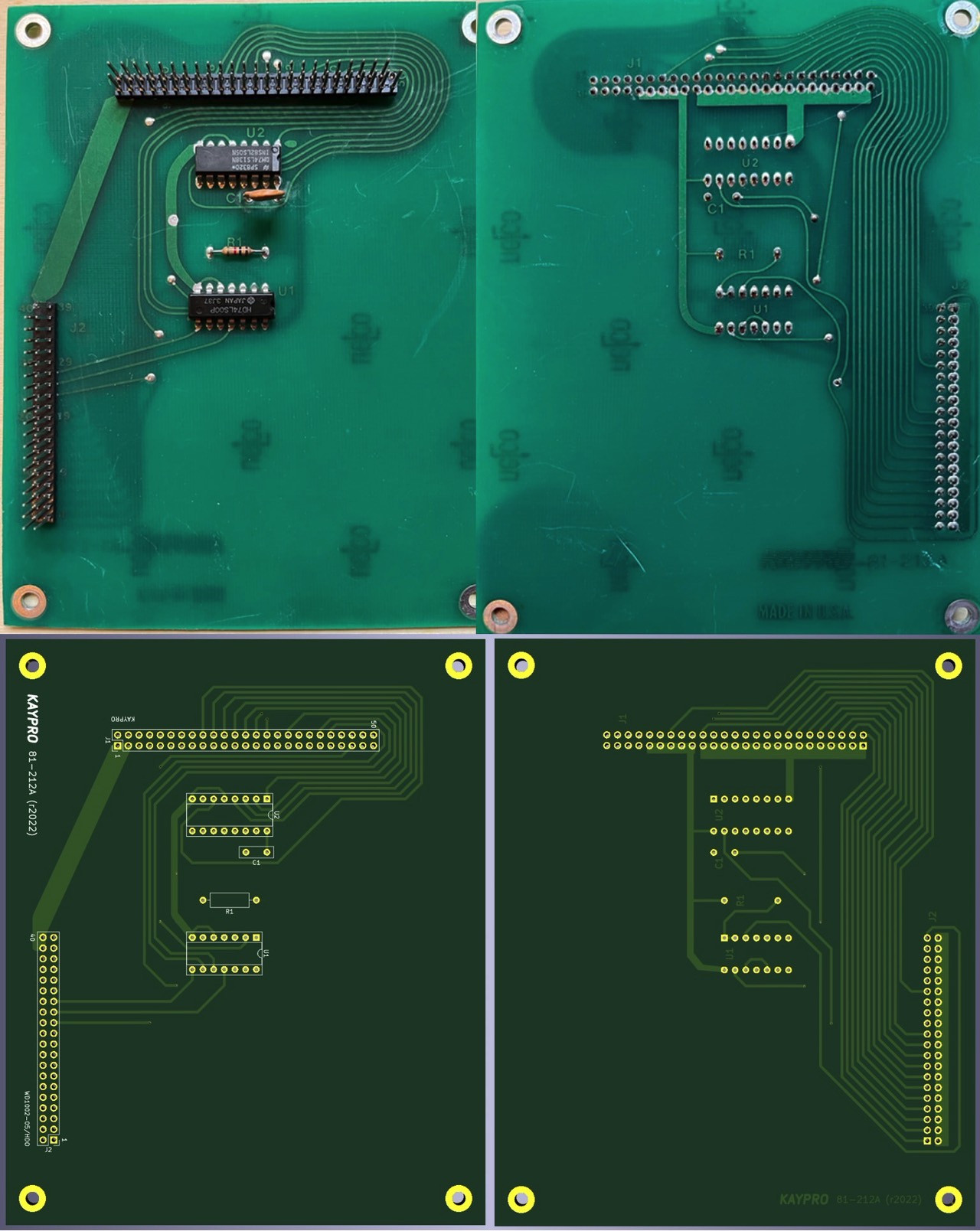
top: K10 ('83), 81-277 / bottom: replika by Douglas Miller
If you want or need to create your own interface board, Douglas Miller has created a replica with KiCad, see above. I have not tested it!
See also the (initial) problems with the Kaypro 10/83.
Hard Disk Drives
According to Gene B. Williams [wg85] page 151, [10 MB] „Winchester“ hard drives from Microscience and Seagate were used in the beginning in the Kaypro 10. According to Mark Minasi [mm91] Microscience offers the models HH-312, HH-315 and HH-612 and Seagate the models ST-212 and ST-412. When selecting the hard drive in the ADVFMT programme, I still found the M10 model from Seagate.
Since Kaypro used several manufacturers for hard drives at that time, you will find almost no information in the literature. Most of the information comes from discussion forums, when someone has opened his Kaypro 10 and looked inside. According to my research, the following manufacturers or types were probably used.
- Shugart: 712
Shugart 712 - Seagate: ST-212
Seagate: ST-212 - Microscience: HH-612

Microscience: HH-612 - Tandon: Possible models are the TM 252, TM 501, TM 502, TM 503
Tandon Winchester hard disk [22] - Micropolis:
Micropolis 10 MByte - International Memories Incorporated: Possible models are the IMI 5006, IMI 5012 and IMI 5018
IMI 5012H
The standard Kaypro 10 hard disk has 306 cylinders and four heads. No matter if it is a Seagate ST-225 (20 MB) or ST-212 (10 MB) hard drive. More than 9 MB are not supported! Furthermore, these 9 MB are logical divided into two drives of 4.5 MB each. When you boot from the hard drive, the first drive is called A: and the second drive is B:. The floppy is C:.
Four read-write heads are used. Heads 0 and 1 access drive A. Heads 2 and 3 access drive B. Disk 1, cylinder (same as track) 0, heads 0 through 3 refers to a critical area of the disk containing the operating System, BIOS, Error messages, and some overlays for screen graphics.Reference: The Kaypro 10 user's guide
I have not tested it, but I could imagine that you could also install an MFM hard drive with, for example, 6 heads. But the ROM will only use 4.
Today (18.12.2021) I changed the hard drive (Seagate ST-412, 10 MB) in my Kaypro 10('83) for a Seagate ST-277R (40 MB). Why? Although the hard disk was extensively tested during the installation of TurboROM and the subsequent formatting with ADVFMT, read and write errors occurred frequently.
My ST-412 "might" be 40 years old by now; this hard drive basically came on the market in 1981. In the first AT BIOS versions, the ST-412 always appears as TYPE 1. It was also used in the first IBM XT 5160.
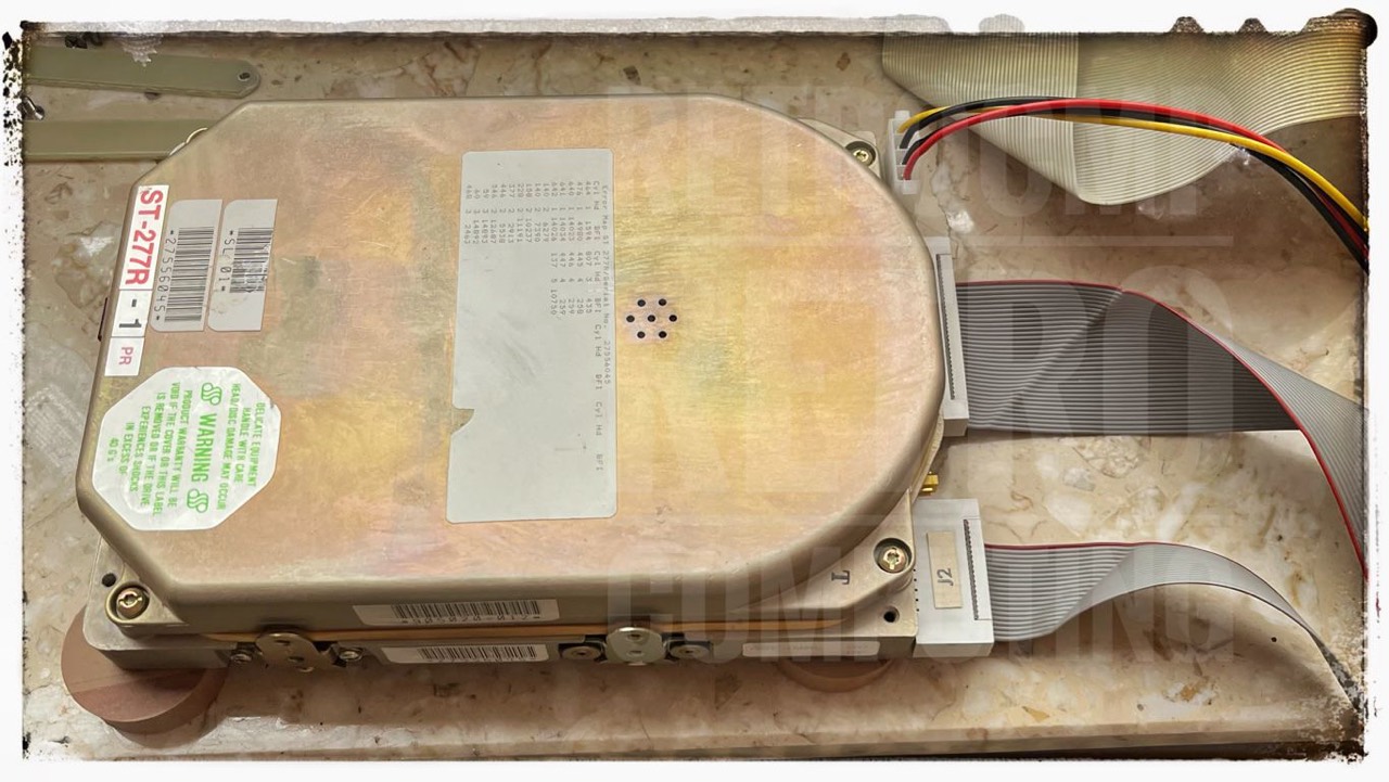
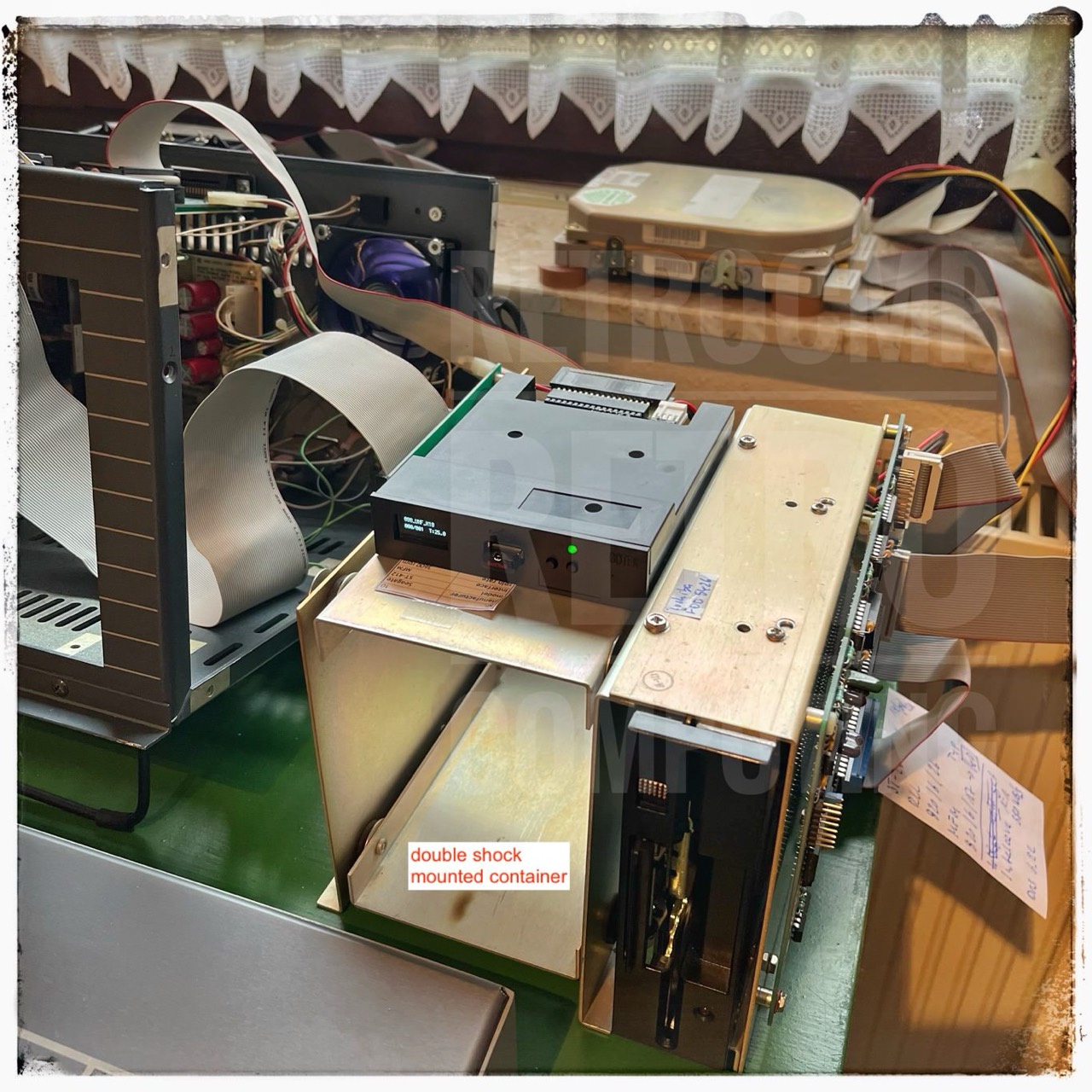
Testing my Kaypro 10('83) (Advent TurboROM) with a Seagate ST-277R and a Gotek/Flashfloppy „floppy“ drive.
The ST-277R is actually intended for RLL, but works just as well with MFM. Instead of 820/6/26, simply use 820/6/17. A total of approx. 40 MB is then available. Of course, this only makes sense with TurboROM or KayPLUS, because the original Kaypro ROM only supports 9 MB. In the formatting program ADVFMT, you can also enter cylinders, heads and sectors manually. Finally, six partitions are available. The sense and purpose of this can of course be discussed.
I now have six hard disk drives (A: to F:) and one floppy disk drive (G:). Of course, this is a little unusual at first, as the floppy drive has always been C: up to now.
Floppy Disk Controller
In nearly all Kaypros the Western Digital FD-1793-02 is installed as floppy disk controller IC. If you need a replacement but can't find an FD-1793, you can also use the MB8876A from Fujitsu.
However the Western Digital's FD-1791-02 was probably used in the very first Kaypros. [39]
Floppy Disk Drives
Preliminary notes about drives
Depending on which Kaypro model and/or BIOS you use, you basically have five different disk types to work with. Whereby the number (4) is actually only listed for the sake of clarity; you don't get to buy preformatted floppy media today.
- SS, DD - 48 tpi - 191/200K
- DS, DD - 48 tpi - 390/400K
- DS, QD - 96 tpi - 784/800K
- DS, HD - 192 tpi - 2.6M - Drivetec
- Gotek (can basically R/W no. 1, 2, & 3) or other
SS = single sided, DS = double sided, DD = double density, QD = quad density, HD = high density
All normal Kaypros (excluding 4X, 12X and Robie) use types 1 and/or 2, so floppies can be easily swapped between them. All disk drives use a write density of 48 tpi. But if you use a 96 tpi drive (80 instead of 40 tracks) in one of your Kaypros the problems start. With a Micro C ROM you are able to read the types 1 to 3 but if you want to write type 1 or 2 you have to be careful. I have described this problem in the following article: Reading, Writing and Formatting 360K Disks in 1.2M (or 720K) Drives. And believe me, sooner or later you will have this problem! And then the floppy is usually screwed up!
Therefore, I personally tend to use only the type 1 and 2, but ... the Gotek (with FlashFloppy firmware) is definitely a useful alternative or addition.
This writing problem was, in my opinion, one of the reasons for the failure of the 4X, 12X and especially the Robie. I myself have a Robie (without HD drives) and find it simply outstanding as a desktop computer.
Manufacturers
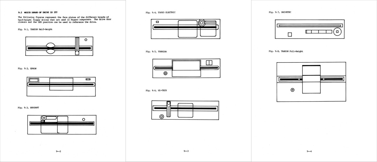
Basically, floppy disk drives from seven different manufacturers were used in the Kaypros.
Note: The references (links) I have added are only examples. In my image collection I have quite "same Kaypro models", but with drives from different manufacturers. The link list is therefore not complete!
- Tandon / Fig. 9.1 / DS, DD / 400 KB
- Epson
- Shugart
- Tokyo Electric / Fig. 9.4 / SS, DD / 200 KB
- Toshiba / Fig. 9.4 / DS, DD / 400 KB
- Hi-Tech
- Drivetec / Fig. 9.7 / DS, HD / 2.6 MB
- Kaypro 4X
- Kaypro 12X
- Robie
- Tandon (full-height) / Fig. 9.8
SS, DD / 200 KB
DS, DD / 400 KB
Problems
Kaypro 10 and 84 drive problems.
The system latch on the Kaypro 10 is tied directly to the drive interface which means that the drive select and side select lines are unbuffered (where have we heard this before). Well, the system latch is a 74LS244 and when it tries to pull down a line tied high with a 150 ohm terminating resistor, it has trouble. Too much trouble.
If your 10 or 84 system is having trouble reading, writing, or formatting disks, you should replace the 150 ohm terminating pack with something greater than 400 ohms. This little fix sure cleaned up the floppy problems on our old 10. [39]
Tandon (Fig. 9.1)
[Issue 13, August, 1983] I've [David Thompson] received a number of calls about Tandon drive alignment, two of them from Tandon itself. According to Tandon, the drives get only a rough alignment before going to OEMs (original equipment manufacturers) like Non Linear. The OEMs are responsible for the final tweaking before shipment. [55]
... but ... The problem with false or incorrect messages also existed in the 80s!
[Issue 14, October, 1983] After reading issue 13 of Micro C, Bill McDonald, chief engineer at Kaypro, called with the latest info on drives (and other things).
He mentioned that Kaypro purchases its drives from Tandon fully aligned, and though they test them before installation, Kaypro doesn't do any alignment. It's Tandon's job to do the complete alignment process. [42]
[February, 1984] Rumors are coming in that Tandon was sending its best drives to IBM and everyone else is getting the dregs so Kaypro is looking for a source of dependable units. [38]
Drive Shunts
              Drive A     Drive B
HM not used    >  <        >  <
spare          >  <        >  <
MS             >  <        >  <
DS3            >  <        >  <
DS2            >  <        >  <
DS1            >  <        >==<
DS0            >==<        >  <
HS not used    >==<        >==<

>  <  open
>==<  closed
Shugart (Fig. 9.3)
[February, 1984] Shugart Floppy Drives: One of the types of drives that Kaypro particularly likes is the Shugart SA 455. Bill MacDonald has had some of these drives reading and writing for 4 days straight without a single disk error. He also mentioned that Panasonic is making these drives for Shugart. [38] p.13
Drivetec (Fig. 9.7)
The Drivetec floppy disk drives are indeed a speciality. While for example in 1982/83 the IBM PC's are partly still sold with the clumsy full height drives (max. 360 KByte), the company Drivetec Inc. from San Jose in California announces in November 1982 a half height floppy disk drive with fabulous 3.33/2.6 MByte (unformatted/formatted). The floppy disk has 192 TPI.
The name is: Drivetec 320 Superminifloppy. The designation "Super" is quite justified! The founder of the company was Herb Thompson, also a founder of Shugart Associates. The same Herb Thompson had built the first floppy disk at IBM in 1967! [1] This was the reason why this new approach was so promising, because he knew this subject very well.
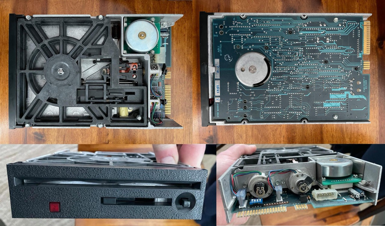
You can clearly see the two stepper motors for coarse and fine positioning of the R/W head.
The Drivetec is the drive Kaypro builds into the Robie, 4X and 12X. That could have been a quantum leap. But unfortunately it wasn't. The Drivetec drives did not succeed in the market and in early 1985 the company went bankrupt and was finally sold to Kodak [2]. Further developments took place here, but these also failed in the end. Drivetec and Eastman Kodak had already signed a licensing agreement in December 1983. [3]
One reason for the non-success of the Drivtec 320 was that the floppy disks had to be factory pre-formatted and they were expensive. They could not be formatted with the Robie, for example. A floppy disk cost at least $7 [4], Chuck Guzis from VCF even speaks of $15. [5]
Why? In addition to the actual data tracks, half a track above and below them is embedded with the so-called BURST information for the servo (fine) stepper. This BURST information is continuously read and evaluated. If both signals are the same, the actual head is positioned exactly on the data track. If this is not the case, the fine stepper repositions the head. The BURST signals are therefore positioning signals for the head. Without these BURST signals, the disks are unusable. The HD drives can of course read and write the data, but they are not able to write the BURST information! And this is exactly what happens in the factory pre-formatting. [67]
Read the following text excerpt at your leisure and you will learn a lot about the Robie and the Drivetec drives.
The Kaypro Column
By David Thompson
This column is about "new." I mean new drives and disks, the Robie variety and a new system, the Kaypro PC.
Robie
Speaking of the Robie, this little duckling has the heart of an 84 system, just the drives, drive clock, BIOS and monitor have been changed. Early feedback on the Robie has indicated that there is a problem with the media (disks).
Everyone expected problems with the drives, I mean, 2.6 meg per disk doesn't leave a lot of room for error (or anything else). However, these drives are similar enough to the current 5" drives that it shouldn't be too hard to add them to standard Kaypros (if there are any standard Kaypros still out there what with 5 MHz, 4 drives, and quad density).
Anyway, we're already working on it, and you'll be hearing more about these right here. Don't expect to see these $500+ drives showing up on the surplus market soon because there is definitely a lot of interest in them. Also, the disks are about $10 each though they look very similar to standard 5" floppies.
The Robie drive can read standard Kaypro II and 4 disks but it cannot write data on these disks — so software transfers are one way only (whereas a quad-density drive can format and write Kaypro II and 4 disks).
Theoretically the Drivetec drives should provide very good data reliability. You see, the drive has two stepper motors. One positions the head to the approximate track location and the other then adjusts the head position slightly to maximize the signal.
Your Disks are All Wet
The biggest problem with standard floppy disks is that the base material is hydroscopic so it expands and contracts depending on the humidity. A disk you format and write at the coast might be difficult to read on the high desert (especially if one of your drives is aligned slightly differently from the other and it's off in the wrong direction).
Blow-drying (use a slightly warm setting) a disk for half an hour, or placing it in a steamy bathroom for a few hours, might be all you need to do to read a balky disk. (Note, if your girl friend catches you using her hair dryer on your disks just tell her you're trying out the latest style in software development. If she doesn't buy that, you probably shouldn't try the same ploy on the guys at the funny farm.) Hold the disk's jacket (not your jacket) open a bit so that the moist or dry air can reach all of the surface.
Anyway, the Drivetec drives compensate for the changes in disk diameter. However, disk size is not the only problem caused by the environment. Most disks are rated for 3 to 3 1/2 million head passes (per track) before the media wears out. Well, some of the disks available for the Robie drives are wearing out after 1 or 2 million passes, but this shortened life appears to correspond with high-temperature (80-100 degrees) and/ or high humidity (90+%).
At 70 degrees and 50% humidity, the disks appear to be unscathed after 4 million passes.
There appears to be some disagreement about who makes the best Robie media. Drivetec feels that Brown disks are best, and the Drivetec branded disks are really Brown. Other folks feel that Maxell disks are the best. We'll have to wait and see. I hope that these Maxell disks are not as abrasive as the standard Maxell 5" disks. Anyway, Brown is supposedly coming up with a revised media package so their disks may be getting better.
Squeezing in 192 tracks per inch (sardines have nothing to complain about) might appear to be foolhardy especially when you realize that they have data between the tracks. They call this data "servo bursts" and if the drive doesn't detect these little off-track marks it doesn't send index pulses to the Kaypro. Obviously you have to purchase the disks pre-formatted, and heaven help the little gnome who passes a magnet over papa's new disks.
Manufacturing
There are four outfits who either are, or soon will be, manufacturing Robie disks: Spin Physics (owned by Kodak), Maxell, Dysan, and Brown.
Kodak (via Spin Physics) is supposedly working on expanding the disk technology. They already have a super density 5" disk and are working on an even higher density version with vertically polarized media. Anyway, the Robie drive is already one level behind the state of the art and will soon be two levels down.
Three outfits will be manufacturing Robie-style drives: Drivetec, Kaypro, and Kodak. Kaypro and Kodak will be manufacturing them under license from Drivetec.
There are currently only about a dozen 12X systems in existance (the Kaypro 10 with a 2.6 meg floppy drive). The engineers at Kaypro are using these 12Xs for software development (such a deal). [8]
Two years later, Thompson writes something about the Drivetec drives again. This time not so enthusiastically. The drives were probably good, but the problem was with the floppy disks!
Excerpt from: Comdex (The Tale Of One Large City)
By David Thompson
Drivetek Strikes Again
Kodak was showing off its latest drive technology. I was interested until I saw the 2.6 meg floppy drive that they were featuring. Wow! I'll bet Kaypro would love to sell Kodak all the Drivetecs they have sitting in the warehouse (both Kaypro and Kodak bought rights to manufacture them). Kaypro even bought a bunch of the drives for its Robie. Kaypro has written off the whole lot.
Other than the fact that they couldn't find disks that worked reliable with the drives (the disk manufacturers saw things a bit differently), the drives were perfect. [8]
Michael Robinson reports:
I worked at Kaypro at the time. The big shortcoming of the Robie was the too-advanced (at the time) high-density drives. The drives would literally eat through very expensive pre-formatted proprietary floppy disks. After a long enough time in the drive, you could hold a floppy up to the light, and see through the directory track where the drive heads had scraped all the oxide off the mylar substrate. Eventually, this was tracked down to a manufacturing defect that left diamond dust on the heads during the polishing step, but by then the Robie was more or less doomed. [7]
The following figure is not to scale, but you can still see that the floppy disk is "bent" between the top and bottom heads. I cannot say whether this is a possible reason for the disk problems; I do not have the technical expertise.
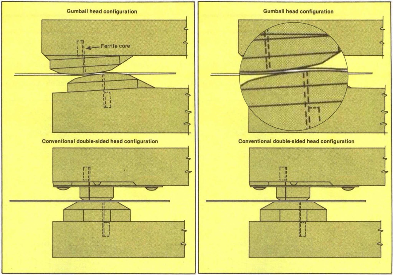
And here is a nice to read summary or abstract by Harvey Patterson (Facebook, Kaypro Computer Users).
... They were Drivetec 320 Super minifloppy drives that used 192 TPI disks. This was a further doubling after 48 TPI DSDD led to 96 TPI DSHD. To keep the read-write head aligned on such tiny tracks, servo data was written between tracks. If the signal was equally strong on both sides of the read-write head, the head was perfectly aligned.
At 300 rpm and a data rate of 250 kbps, a double-sided disk has an unformatted capacity of 500 KB. (Kaypro formatted 10 sectors per track, for a formatted capacity of 400 KB, which was 391 KB after the FAT, etc.) With identical RPM and data rate, switching from 48 TPI to 96 TPI doubles capacity to 1 MB, and going to 192 TPI redoubles it to 2 MB. IBM chose to also double the data rate to 500 kbps for DSHD, which would have doubled unformatted capacity to 2 MB, except that they also increased the RPM to 360, reducing it to ~1⅔️ MB. (Formatting 15 sectors per track reduced it to 1.2 MB formatted.) Drivetec also doubled the data rate to 500 kbps, producing an unformatted capacity of ~3⅓️ MB. Herb Thompson, president of Drivetec, said they would be formatted with 30 256-byte sectors per track (equivalent to IBM's 15 512-byte sectors per track) in the July 1983 edition of MINI-MICRO SYSTEMS, exactly doubling IBM's formatted capacity to 2.4 MB. That was the 3230F disk. Kaypro went with the 3217F disk, which was formatted with 17 512-byte sectors, for a formatted capacity of 2720 KB or 2.65 MB, and they listed them as being 2.6 MB drives.
Besides needing 192 TPI disks, the drives couldn't write the servo data between tracks, so disks had to come pre-formatted.
Kaypro and Kodak licensed the rights to manufacture Drivetec 3.3 MB drives. Drivetec had a 6.6 MB drive in the works when they went bankrupt and got bought out by Kodak. Those drives used 384 TPI (320 track) disks.
Despite being designed with a "gumball" head instead of a square head, which was supposed to prevent the head from scraping the disk, Kaypro Robies were known for scraping the recording layer off of disks. It was tracked down to diamond dust being left behind after the grinding process, after Kaypro had a warehouse full of drives manufactured. Betting on Drivetec was a costly mistake for Kaypro which, along with being slow to the PC clone market, may be why they didn't survive.
Between needing to buy special, pre-formatted disks for somewhere between $7 and $15 per disk, to the bad reputation that the drives got for destroying the disks, Drivetec went bankrupt and the format died. Super capacity floppy disks weren't tried again until Insite came up with an alternative to using servo data between tracks to keep the read-write head centered on tiny tracks, namely using a laser for tracking. This enabled an incredible 120 MB capacity 3.5" disk, in tandem with switching to perpendicular recording. The LS in LS-120 stands for "laser servo". Magnetic disks with optical tracking were known as "floptical". This concept led to the ZIP-100/250/750, LS-120/240, UHD144, and Sony HiFD 150/200 MB disks.
Video
Cathode Ray Tube - CRT Danger to Life

Youtube: Discharging the CRT in a compact Macintosh. A lot of safety advice is given in this video! If you are not sure what you are doing, KEEP YOUR HANDS OFF! I warn you explicit!
Video Board
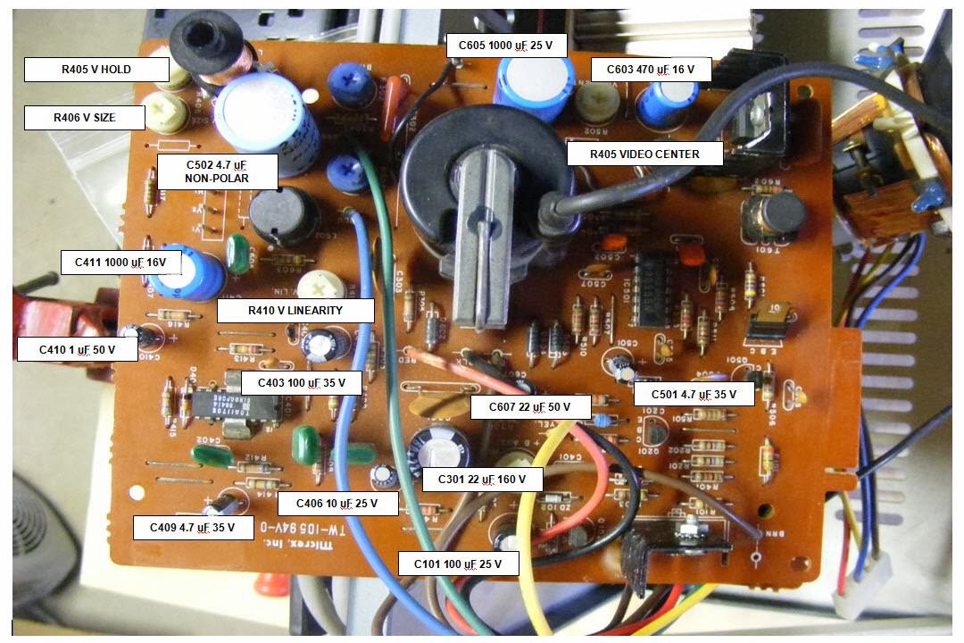
Power Supply Unit (PSU) Danger to Life
They have used several different power supplies [for the Kaypro II's] during the initial production. All have been small switchers producing +5V, + 12V, and -12V. Some have not provided very good regulation (the video image shrinks noticeably during disk accesses). Some of the early power supplies appeared to be quite sensitive to spikes on the power line. I notice that there is a MOV (metal oxide varister) on mine so it appears that they are aware of that problem. All the power supplies have been jumperable for both 110V and 220V AC. [49]
The oldest (and noisiest) Kaypros have an AC cord that is permanently connected the back panel (not a plug and socket). These units don't have an AC line filter (the AC wires go directly to the on/off switch). If you have one of these units, the first thing you need to do is purchase an AC line filter. You can get one that mounts on the inside of the cabinet, then you connect very short leads from the power cord to the filter. Or, even better, you can purchase a new cord and filter combination (the filter has a power socket built in). [50]
Kaypro is using three different brands of power supplies at the present time. These are Astec, Boschert, and Cal D.C. These three power supplies are interchangeable with any of the Kaypro computers, if the power supply being changed is a new one from the factory. If a power supply is removed from a 2/83 or a 4/83, and it's going to be used in another computer, it MUST be used in a 2/83 or 4/83. The power supplies used in 2/83 and 4/83 computers are not interchangeable with other Kaypro computers. [18]
The Kaypro 10s have a 75 watt switching power supply. The IIs and 4s have had a smaller one, but since Kaypro is purchasing supplies in such quantity, the 75 watt units are now as cheap as the littler ones. Now there should be no more screen twitching when the drives fire up. [23]
... In fact, all you need for any Kaypro (II, 4, or 10) is +12V, +5V, and -12V. The supply in the Kaypro II and 4 can supply about 6 amps of +5V (although the system uses only about 3 amps) and about 3 amps of +12V for the drives. You only need about 0.1 amp of -12V. The Kaypro 10 needs a couple more amps of +12V during winchester start up. [38] p.47
Astec
The Astec power supplies can be used for 110V as well as for 230V. For this you only have to change the (massive) jumper with the flag "110V". [24]

You can use this power supply up to 55W or 75W (with cooling fan). In the meantime I have replaced the old RIFA interference suppression capacitors and all other capacitors too.
I have a second one of this power supply unit (Astec AA 12450) as a reserve; with all capacitors changed.
The following power supply (AA 12350) - from my Kaypro II (from '83) is almost identical to the AA 12450 for the Kaypro 10. However, the AA 12350 is only rated to a maximum of 65W. For the time being I have installed a completely revised AA 12450 in the Kaypro II, because I want to replace all capacitors; at least however the old RIFA interference suppression capacitors.
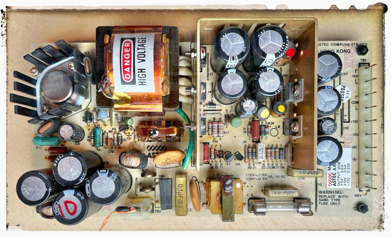
Former address: Astec, 1101 Space Park, Santa Clara, CA 95050, 408.727.3350
Boschert

Former address: Boschert, 384 Santa Trinita Avenue, Sunnyvale, CA 94086, 408.732.2240
California DC
You can immediately recognize the California DC power supply by the blue color of the circuit board. At the bottom left are two ceramic resistors, which will get very, very hot. You burn your finders on it, believe me!
And it is precisely this negative characteristic that, in my opinion, results in the connector header being on the left and the two resistors mentioned being on the right. This allows the enormous heat (on the right) to rise outside the mainboard. Enormous heat must have built up in the housing of the devices with this power supply unit. How could this even work in summer?
In the later power supply units (Astec, Boschert), the connector strip is on the right, so the power supply unit is turned round.
But the special feature of this power supply is the rotatable resistor at R26 (10K, 204). When I also checked the power supply during my review of the Kaypro II (#4,037), the output voltage on the 12V line was only 10.5V; definitely too low. Upon closer inspection I found the label "V ADJ" at R26. Is this perhaps the abbreviation for ADJUST? I only minimally turned the screw and already the voltage was at 12.3V; then checked the 5V line, it is at 5.5V. Great!
There are two blue versions that have been used in the (first) Kaypro II. [45, p.10] The difference are the 110/230 V jumper sockets (bottom middle). They can be parallel or perpendicular to each other.
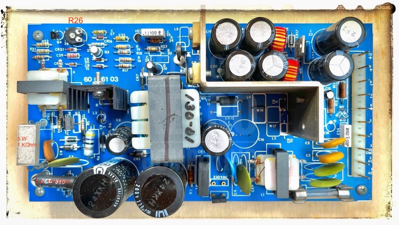
The power supply used in the KAYPRO II computer is either a California DC power supply or a Boschert power supply. Both supply plus and minus regulated 12 VDC and +5 VDC and dissipate approximately 60 watts.
One important difference between them is that the Cal DC power supply has two five-watt power-dissipating resistors located in the upper corner (these are the 1K & 10K Ohm rectangular ceramic resistors) that normally get quite hot. Therefore, the power supply cables nearby should be tied down behind the power supply circuit board, or damage could result. [45, p.7]
Former address: Cal DC, 2150 Anehor Court, Newbury Park, CA 91320, 805.499.3621
Changing the old PSU
If you have absolutely no intention to refit or repair your old Astec or Boschert power supply, or you can't, then with a little skill you can install a completely new power supply. Here are two PSUs that are used by many Kaypro users. For the Kaypro II & 4 the PSU must have 65W, and 75W for the Kaypro 10.
A new power supply is usually also much cheaper than changing the capacitors, etc. on an old one. For example, two large capacitors of type 250V, 220uF, 22x40mm for my Boschert cost about 20 EUR! For about 40 EUR you get a completely new power supply.
- MEAN WELL RPT 75B
- MEAN WELL RT 85B
Both PSUs have -12V, +12V and +5V DC output. According to MEAN WELL specification you can use the 75B up to 72W with convection and 100W with force air. This should fit even for a Kaypro 10 because it has a vent.
A small problem are still the holes in the back panel of the Kaypro for mounting the power supply. Either you have to drill new holes here or mount the new smaller power supply on a plate that has the same dimensions as the older larger one.
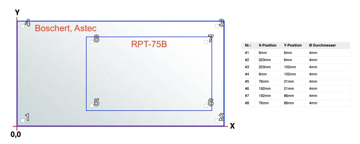
Information
I have done a lot of research on the internet, but I have not been able to find any more information like schematics, etc. There is general information on BITSAVERS for the Astec and Boschert power supplies, but not for the specific Kaypro power supplies; only the Astec AA12090 for the TRS-80 Model 4 (Tandy P/N 8790043).
Regarding the switching from 110V to 220V, you should also watch the following video from High Voltage Hot Dog on Youtube.
The member "k6whp" from VCF made an overview of the Kaypro wiring harness (Use at your own risk).
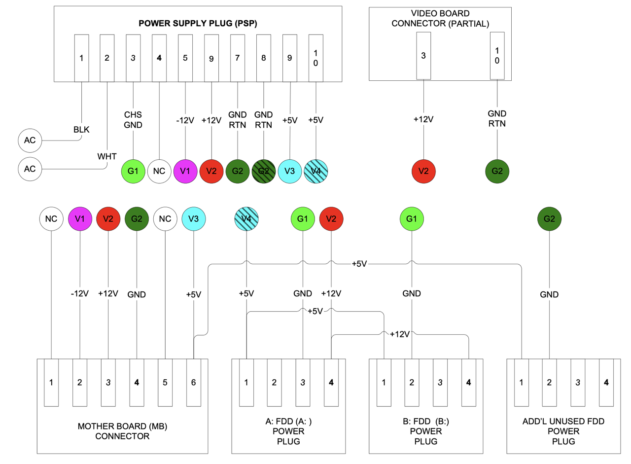
Cabinet
The dimensions of the Kaypro's have not changed since the first model: W/H/D = 18.0/8.0/15.5 inch. The cabinet is made of anodized aluminium. [79]
Keyboard
You will find a veritable cornucopia of information about keyboards at Telcontar.net.
According to Frank Rahman, who has a very extensive Kaypro collection, there are basically three keyboard models:
- Key Tronic
- SMK
- Maxi-SWITCH
According to the information I have, the SMK has no BELL G key, both others have.
Key Tronic
Key Tronic is a leading electronics manufacturing service provider in Spokane Valley, Washington, USA.
The special feature of the Key Tronic keyboard is the capacitive sensing. You can find very detailed information on this at Telcontar.net.
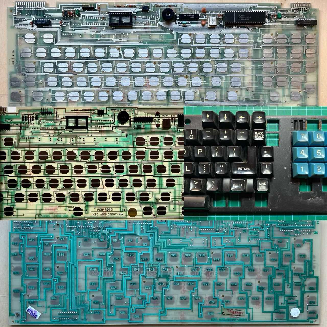
This keyboard has a BELL G key; not shown here! The Key Tronic keyboards have a major disadvantage:
There was simply a sponge pad with a conductive-coated Mylar plastic sheet on the switch plunger, and two half-moon trace patterns on the printed circuit board below. As the key was depressed, the capacitance between the plunger pad and the patterns on the PCB below changed, which was detected by integrated circuits (IC). [95]
These sponge or foam-and-foil pads deteriorate or disintegrate with age. I have two keyboards that need to be renewed. You can buy these pads from tex ELEC.
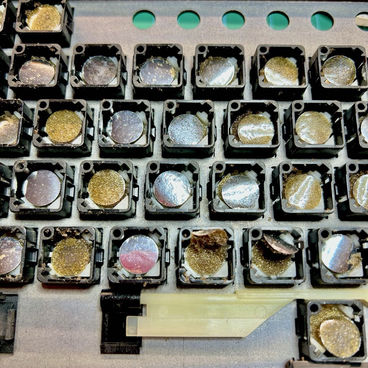
The old pads are simply lifted from below with pointed tweezers and then often pop out on their own. Then insert the new pad. You do not have to glue them. This process is very simple, but it does take time.
Removing the complete keys is very easy if you use the following trick. You have to press the key and only then the two tiny clamping snaps on the back can be pressed together (to the inside). If you do not press the key, there will be resistance on one of the clamping snaps and you will not be able to remove the key.
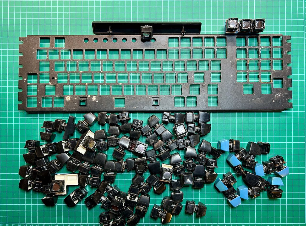
The disassembling takes me round about 10 minutes. The black metal construction is heavily corroded in some places. However, I cleaned everything with warm soapy water. I also cleaned the corroded areas with a toothbrush. But nothing more. Now it's time for the buttons with the pads. That will probably take 1-2 hours. I'll see.
Basic procedure: First remove all pads, then clean the buttons with a microfibre cloth and some isopropanol and then insert the new pads. Replace all pads. Even if the silver contact surface shines perfectly, everything underneath is crumbled, at least in my case.
Removing the pads and the rough cleaning with a toothbrush took almost 60 minutes. I was accompanied by the music of Chris Rea, Celtics from 1979, played from a music cassette on my Pioneer CT-979 with my Harman/Kardon 656 - simply marvellous.
Finally - after 4 hours - everything is done and the new keyboard is working fine.
SMK
According to Telcontar the SMK Corporation is a Japanese electronics manufacturer that produced keyboards back then.
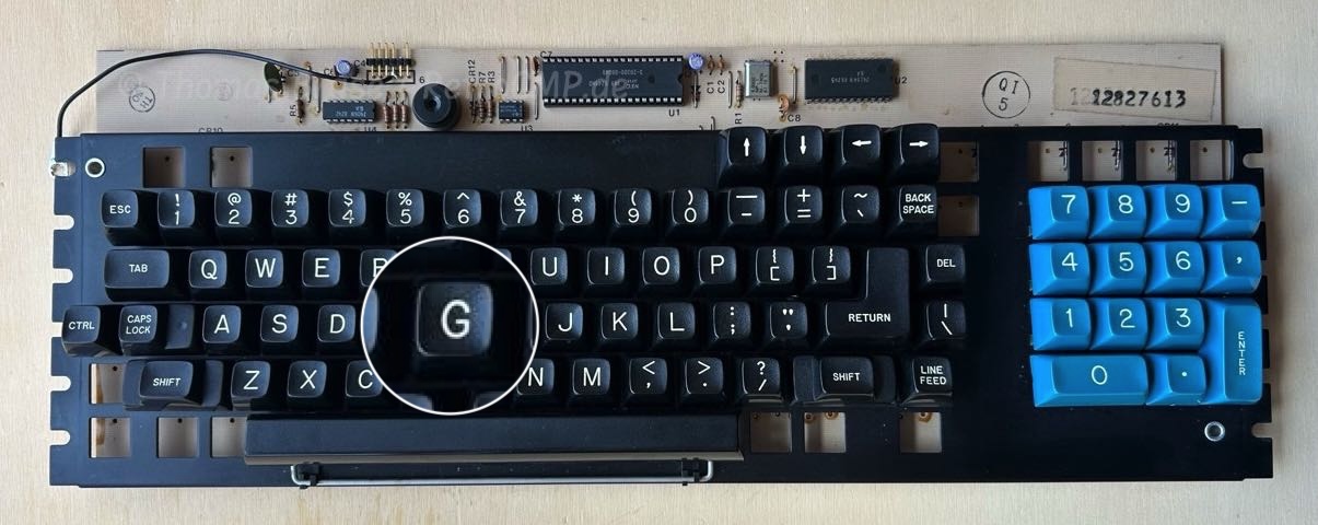
According to Frank Rahman and Telcontar there are C, D, E, Y and Z models. I have a C model.
Maxi-SWITCH
According to Telcontar the Maxi-Switch Company (later Maxi Switch Inc) was an American switch and keyboard manufacturer in Minneapolis, Minnesota, USA.
Currently (May 2025) a total of 100 NOS Maxi-SWITCH keyboards are being sold on eBay US. Unfortunately the keys have a brown colour. But better brown than a not working keyboard.
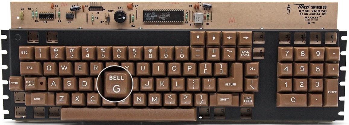
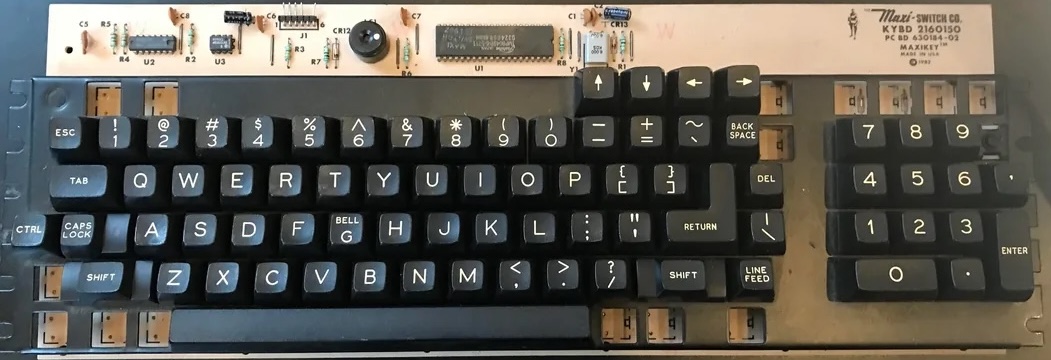
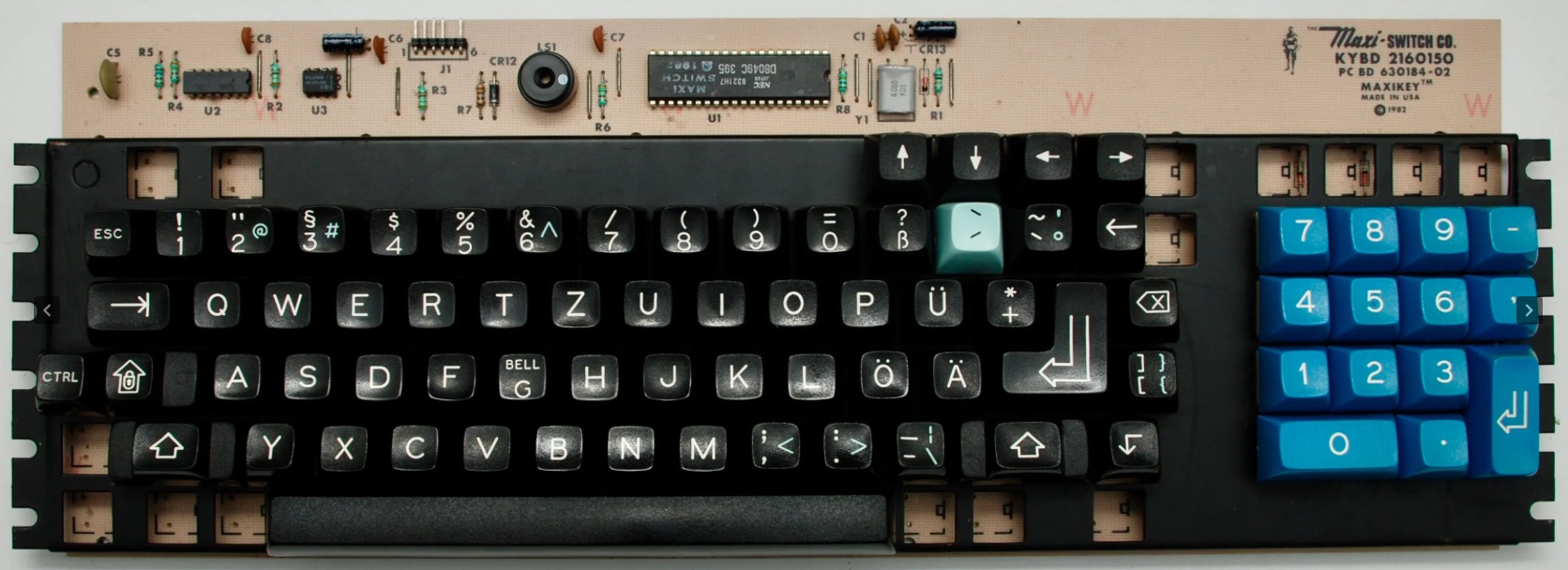
All three (6000 series) keyboards above have the same part number 2160150 and PCB code 630184-02. Only the buttons have a different colour.
According to Telcontar "the 6000 series is believed to be a variant of the mechanical portion of SMK JM-0400 series".
A Maxi-SWITCH keyboard with black keys for example is in my Kaypro 4/84.
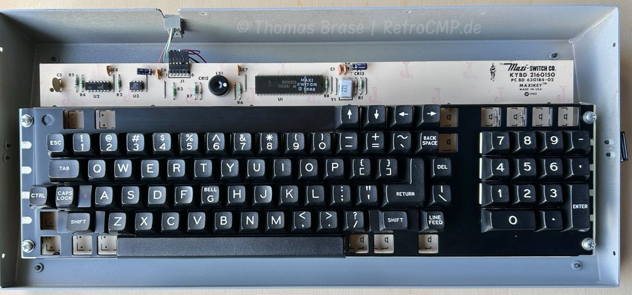
Keyboard Connector
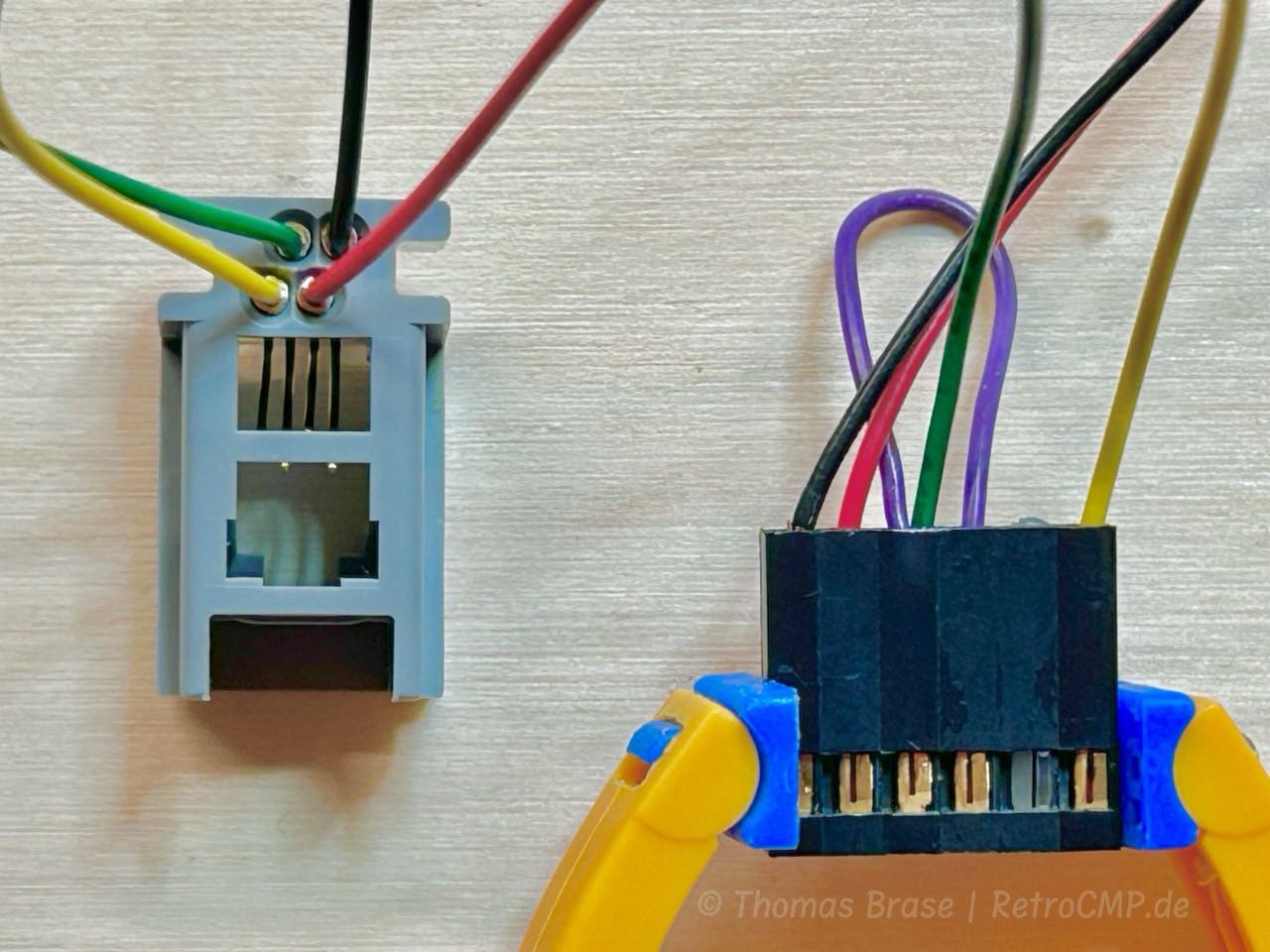
If you have all the parts and know how to do it, repairing a broken RJ45 socket takes a maximum of 10 minutes.

You need a new keyboard socket for your Kaypro?
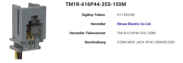
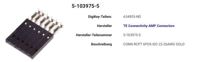
You can also try: Free Hanging - Panel Mount - Rectangular Connectors - Electronic Components - Distributor DigiKey.
Bits and Pieces
Have a look at Bits and pieces by Frank Rahman.
Screws
- Tension latch (4 pcs): 4-40, 3/" (9,4 mm), UNC
- Keyboard (6 pcs): 4-40, 5/16" (7,9 mm), UNC
Tension latch
Problems
General
Broken Solder Joint
You will encounter this problem in many areas. Thick soldered wires and especially if they are exposed to mechanical stresses break off in their soldering contact over time. This is also the case with the video PCB in my Kaypro II (#010-408)
My monitor only displayed a vertical bright line in the center of the screen at irregular intervals. After about 40 minutes, I found the error. Completely trivial. The video circuit board had a broken solder joint, see magnifier.
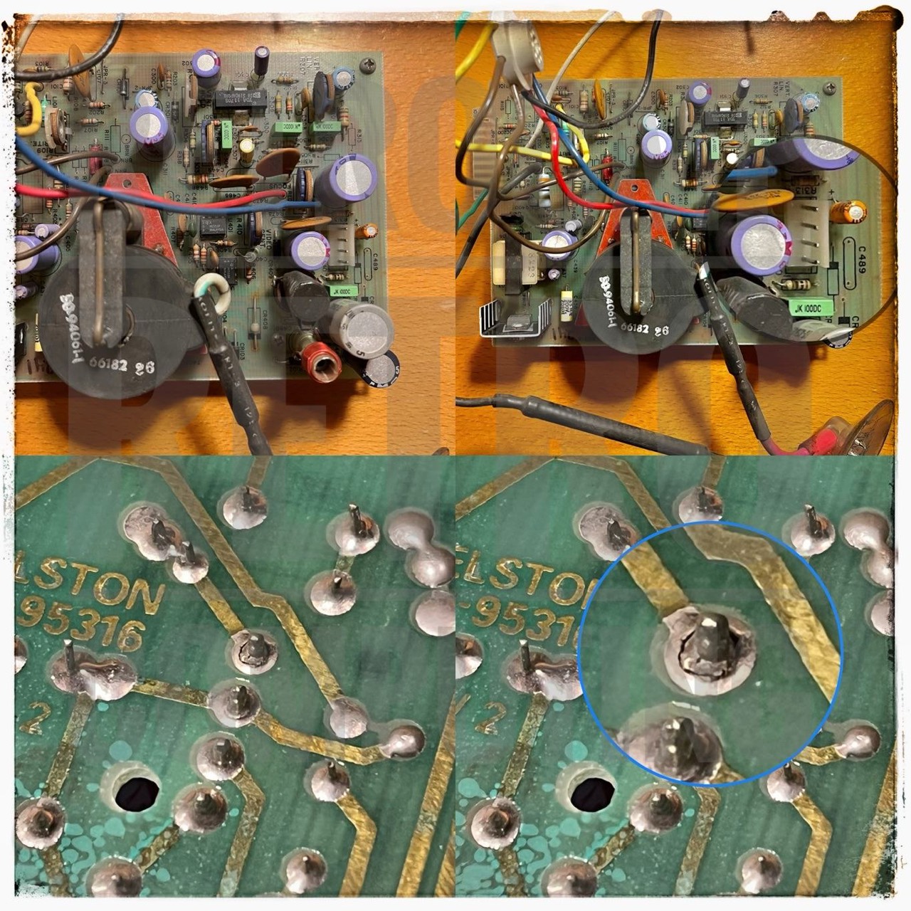
Kaypro II
With the Kaypro II, especially when changing from the vertical to the horizontal arrangement of the floppy drives, heat problems are often described in the literature. This can be read in issues 10 and 11 of Micro Cornucopia, among others.
The next problem concerns only the early Kaypro II with vertical drives:
Furthermore, the display picks up a great deal of noise that appears as raster scan-lines that run across the face of the CRT when the disks are accessed. That can prove disconcerting if you are trying to follow a user help-menu. And, it's not limited to isolated incidents; it happens every time the read-write head of the disk is accessed. The problem is something that should be looked into, because the fact that the screen "hears" the controller circuitry indicates that it is noisy from an RF standpoint.
Kaypro 10
In the early days, there have been problems with the Kaypro 10 ('83) with the hard drive, the interface board and the BIOS.
The Kaypro 10 had been on the market about five months when I [Steve McMahon] wrote this review [May 1984]. The machine I reviewed (a late November 1983 model) was very different in both the software bundle and implementation of the operating system from what Kaypro was shipping in July of 1983. The software bundle had gone through several major changes, the BIOS (basic input/output system) was in revision "F;' and the monitor EPROM (erasable programmable read-only memory) and the hard-disk interface board had each been changed. Several system utilities for use with the hard disk had been revised to work with the new EPROM and interface.
The BIOS, EPROM, interface board, and utility changes were necessitated, a Kaypro spokesperson said, to rectify a problem that only a few machines might have: incorrectly reporting hard-disk errors. In addition to preventing inaccurate reports of read faults, the changes also appeared designed to prevent a possible hard-disk reset error, an independent comparison of the old and new interface card suggested.
Kaypro is shipping kits to all its dealers that are necessary to fix any las already sold that might have the hard-disk difficulties, and no charge will be made for the repairs whether in or out of warranty, the Kaypro spokesperson said. [13]
According to InfoWorld magazine [14] and [15], Tandon was the first hard disk supplier for the Kaypro 10 and there were problems with the hard disk in the early days. At times, production had to be slowed down and a new EPROM kit was brought to market, which was supposed to fix 80% of the problems. In the course of these problems, a second hard disk supplier (Microscience) was integrated into the production of the Kaypro 10.
Downloads 
- Douglas Miller: Kaypro 10 ('83) Interface Board (KiCad)
- Thomas Brase: Plus-4 Decoder for Kaypro II & Kaypro 4 (Gerber, v1.1)
The use of the Plus-4 decoder is at your own risk and responsibility. If in doubt keep your fingers off! It does NOT work with the Kaypro 10!
Information
Here you will find all my gathered information about the CP/M Kaypro's.
Reference
- (↑) BYTE, March 1983, page 78
- (↑) InfoWorld, December 16, 1985, page 18
- (↑) Computerworld, December 5, 1983, page 141
- (↑) Popular Science, October, 1985, page 129
- (↑) https://www.vcfed.org/forum/forum/collections-community/your-vintage-computer-collections/36437-kodak-verbatim-6-6-mb-floppy-drive?p=445202#post445202
- (↑) Mini-Micro Systems, July 1983, page 219, Half-height minifloppy stores 3.3M bytes, Herb Thompson
- (↑) https://www.old-computers.com
- (↑) Micro Cornucopia, #28, Februar 86, page 22
- (↑) Micro Cornucopia, #20, October 1984, page 26
- (↑) Herb Thompson, Half-hight minifloppy stores 3.3M bytes, 1983
- (↑) KayPLUS ROM Upgrade for Kaypro 10, 2-84, 4-84, May, 1986, page 58
- (↑) Micro Cornucopia, #14, October 1983, page 21
- (↑) BYTE, May 1984, page 224
- (↑) InfoWorld, October 3, 1983, page 8
- (↑) InfoWorld, November 4, 1983, page 34
- (↑) https://www.vcfed.org/forum/forum/genres/cp-m-and-mp-m/36295-kaypro-10-help?p=515523#post515523
- (↑) Pro/Files, January 1988, page 61
- (↑) Kaypro Technical Manual (1484-F, 1985)
- (↑) Terry Stewart - https://www.classic-computers.org.nz/blog/2010-01-26-keyboard-problem-on-kaypro.htm
- (↑) Member Sharkpuncher - http://forums.bannister.org
- (↑) Member rfka01 - http://forums.bannister.org
- (↑) BYTE, May 1984, page 207
- (↑) Micro Cornucopia, #14, October 1983
- (↑) Chiltons' Guide to Kaypro Repair and Maintenance, October 1985, page 112 [wg85]
- (↑) BYTE, October 1984, page 515
- (↑) BYTE, May 1984, page 183
- (↑) BYTE, August 1984, page 316
- (↑) CO-POWER-88 Advertisement, source and date unknown
- (↑) Micro Cornucopia, #33, January 1987, page 57
- (↑) Kaypro User's Guide Addendum, September 1984, page 2
- (↑) Micro Cornucopia, #12, January 1983, page 25
- (↑) Micro Cornucopia, #18, June 1984, page 24
- (↑) Micro Cornucopia, #21, December-January 1985, page 42
- (↑) Micro Cornucopia, #27, December 1985, page 90
- (↑) Micro Cornucopia, #27, December-January 1986, page 84
- (↑) Micro Cornucopia, #22, February-March 1985, page 81
- (↑) Micro Cornucopia, #24, June-July 1985, page 35
- (↑) Micro Cornucopia, #16, February 1984, page 12
- (↑) Micro Cornucopia, #19, August 1984, page 20
- (↑) Micro Cornucopia, #18, June 1984, page 3
- (↑) Micro Cornucopia, #17, April 1984, page 20
- (↑) Micro Cornucopia, #14, October 1983, page 20, 21
- (↑) Micro Cornucopia, #14, October 1983, page 2
- (↑) Micro Cornucopia #9, December 1982, page 2
- (↑) Kaypro II Dealer Reference Guide, 1982, page 17 & 18
- (↑) Member jaquinn from VCF / https://photos.google.com/share/AF1QipM1RYLoml2v-w2u6kwcMACpEpAtpbCXy-pxDSoMJEsx3_M0FyFTR_zNUrZnBNW12A?key=NEZGVEtESUlkbzVXUG5Tby04Sk9jVXljeEVfdlR3
- (↑) STANDARD MICROSYSTEMS CORPORATION, Floppy Disk Controller/Formatter FDC1791-02, FDC 1792-02, FDC 1793-02, FDC 1794-02, FDC 1795-02, FDC 1797-02
- (↑) Pro/Files, June 1984, page 83
- (↑) Micro Cornucopia, #10, February 1983, page 26
- (↑) Micro Cornucopia, #15, December 1983, page 30
- (↑) Chris Singleton, Duncan, BC, Canada
- (↑) Adam Vaughn , https://www.electronixandmore.com/adam/temp/kaypro10/kaypro10_board2.jpg
- (↑) BYTE, August 1984, page 316
- (↑) Micro Cornucopia, #21, December-January 1985, page 43
- (↑) Micro Cornucopia, #13, August 1983, page 22
- (↑) Newsgroup: Kaypro 4 ('84) Hardware, Marc Wilson, Feb 13, 1990 (https://mdfs.net/Archive/info-cpm/1990/02/13/184752.htm)
- (↑)Micro Cornucopia, Number 17, April 1984, page 20
- (↑) https://forum.vcfed.org/index.php?threads/schematic-for-kaypro-ii-with-wd1791-fdc.62436/post-754732
- (↑) SWP CO-POWER SYSTEM GUIDE (for Kaypro 2X, 2/84, 4/84, 10 with Universal Board), August 1985, page 5
- (↑) Computer & Electronics (formerly Popular Electronics), June 1983, page 58
- (↑) Brochure: Kaypro, the Complete Business Computer, 1983
- (↑) Facebook - Kaypro User Group: Ruben de Rijcke - https://www.facebook.com/groups/580355602847013/permalink/769909910558247/
- (↑) InfoWorld, August 15, 1983, page 34
- (↑) Kaypro Kaynet User's Guide, 1983
- (↑) Kaypro 84, Theory of Operation, Micro Cornucopia, 1984
- (↑) Micro Cornucopia, #30, Jun-Jul 1986, page 44
- (↑) Herb Thompson, Half-height minifloppy stores 3.3M bytes, MINI-MICRO SYSTEMS, July 1983, page 219
- (↑) Courtesy Chris Singleton, Duncan, BC, Canada
- (↑) https://t-lcarchive.org/kaypro-2x/
- (↑) Pro/Files, March 1985 , page 30
- (↑) TJ Demonte, Facebook, Kaypro Users Group
- (↑) Ron Maxwell, Facebook, Kaypro Users Group
- (↑) Advent TurboROM manual
- (↑) Kaypro Hardware Bulletin, FSB 004, Mar 1, 1983
- (↑) Micro Cornucopia, #15, December 1983, page 2
- (↑) Email correspondence with David Kay from 09/17/2022
- (↑) Riding the biggest wave, IEEE Spectrum, Dec. 1984, page 66ff
- (↑) Radio Electronics, April 1983, page 28
- (↑) InfoWorld, Oct. 31, 1983, page 109
- (↑) Facebook - Kaypro Computer Users: Ken Segler
- (↑) Facebook - Kaypro Computer Users: John M Holmes Jr
- (↑) Vince Marchand, France
- (↑) boskug, The Boston Kugel, March 1985, page 4/5
- (↑) Stephen Stone, California, USA
- (↑) LaVerne Kreklau
- (↑) Kaypro Technical Manual (1484-C, 1984)
- (↑) Micro Cornucopia, #20, October 1984, page 66
- (↑) Frank Rahman, Springfield, Illinois, USA
- (↑) Micro Cornucopia, #19, August 1984, page 60
- (↑) eBay sales image
- (↑) Member bcc from VCF / https://forum.vcfed.org/index.php?threads/kaypro-and-kayfrehd-as-a-hard-disk-module.41196/post-761821
- (↑) Mike Douglas, Facebook, Kaypro Computer Users
- (↑) Internal Memo from James Harrison to Lead Service Center Technican; Additions To KayPro Product Line; Aiugust 2, 1984
- (↑) PROFILES, Volume 2, Number 1, July 1984, page 45
- (↑) https://en.wikipedia.org/wiki/Key_Tronic
- (↑) Design News, 39/24, 12-19-1983, page 16
My Series About the KAYPRO
--> Go to Part 1 : Versions
--> Go to Part 2 : Hardware
--> Go to Part 3 : 8K EPROM Modification
--> Go to Part 4 : Formatting a Hard Disk
--> Go to Part 5 : USER areas
--> Go to Part 6 : MASMENU - Master Menu
--> Go to Part 7 : Terminal
--> Go to Part 8 : KayPLUS ROM
--> Go to Part 9 : Advent TurboROM
--> Go to Part 10: Multicopy Plu*Perfect
--> Go to Part 11: The Kay Family & Company
--> Go to Part 12: Kaypro Design Views
--> Go to Part 13: Micro Cornucopia
--> Go to Part 14: Repairing a Kaypro II
--> Go to Part 15: Kaypro Collections
--> Go to Part 16: Kaypro General
--> Go to Part 17: Kaypro Robie
--> Go to Part 18: MFM-Emulators
--> Go to Part 19: Roadrunner ROM
--> Go to Part 20: Software
--> Go to Part 21: FAQ
--> Go to Part 22: Kaypro Virtual
--> Go to Part 23: Formatting a Floppy Disk
--> Go to Part 24: ROM, EPROM
--> Go to Part 25: Kaycomp