<-- Back to Part 13: Micro Cornucopia
--> Go to Part 15: Kaypro Collections
Repairing a Kaypro II
Last revision of this page: December 10, 2024
- Function and Problem Analysis
- 18.03.2022: Day 1 - General
- 19.03.2022: Day 2 - ROM and CHARACTER ROM
- 20.03.2022: Day 3 - Mainboard IC's (1)
- 21.03.2022: Day 4 - Mainboard IC's (2, 3)
- 22.03.2022: Day 5 - Video RAM, Mainboard IC's (4, 5)
- 23.03.2022: Day 6 - Mainboard IC's (6)
- 25.03.2022: Day 7 - Changing Capacitors
- 27.03.2022: Day 8 - Reassembling and Test
- 28.03.2022: Day 9 - Keyboard
- 17.04.2022: Day 10 - Floppy Disk DRIVES and DRIVE FIX MOD
- 17.04.2022: Day 10 - Some Pictures
- 21.05.2022: Day 11 - A New Mainboard CRT ABS/Copper Shielding
- 81-110-B1 (#36311) - Mainboard
- Information
- References
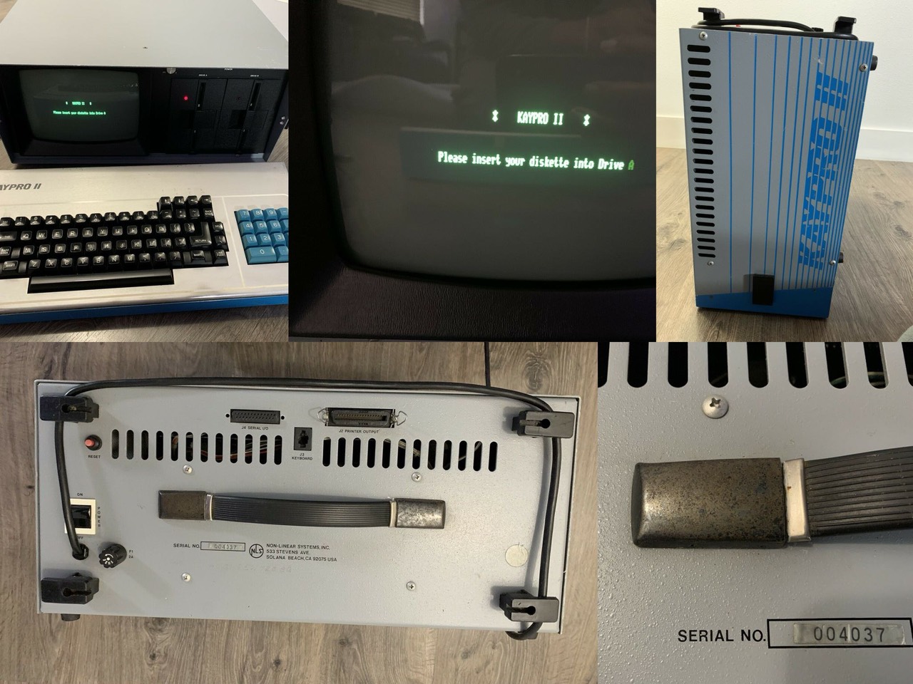
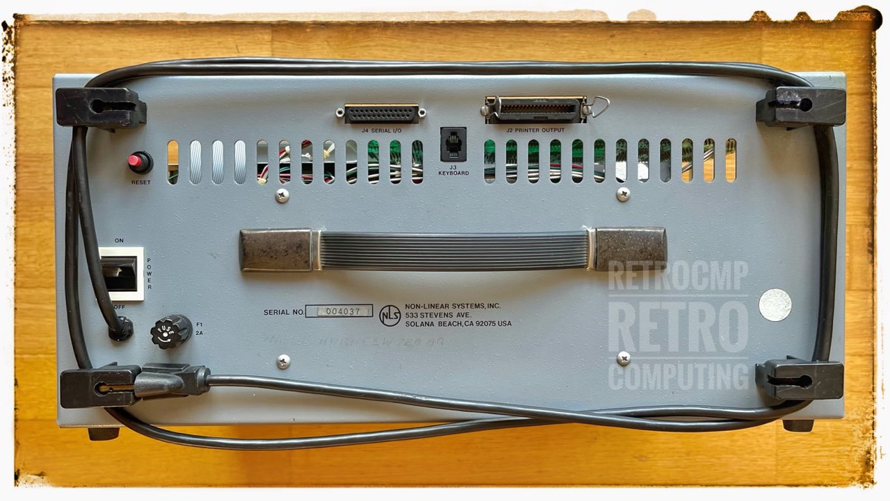
In early March 2022, I purchased a very early model Kaypro II on eBay (US). It has the serial number #4037, has vertically mounted floppy drives, a fixed power cable and the brightness control is in the front. Furthermore, this early version has a network toggle switch with a "white border". The later models have a completely black toggle switch. Another difference from the later models is the rotary socket for the 2A fuse.
The interior of this early Kaypro II is also special. The mainboard is an 81-180-A and the floppy controller is an 1791 (not an 1793). From this equipment you can see that this Kaypro II is really one of the first.
And now the big question, does it work or not. On the eBay sale pictures you could only see the BIOS message. After all, it can't be completely defective. So, let's get to it.
Function and Error Analysis
Regarding repair and troubleshooting of a Kaypro II, 4 and 10, be sure to read the book by "Williams, Gene B. (1985): Cilton's Guide to Kaypro Repair and Maintenance" [1]. It is a real treasure trove of information.
18.03.2022: Day 1 - General
Today the Kaypro II was delivered. It was well packed, nothing rattles and the CRT is "externally" intact. So far so good.
The upper housing plate has various scratches but basically it looks quite good for its 40 years. There is some rust on the handle. The cable for the keyboard is missing. No problem, I have enough of them.
In total, I let the Kaypro - without the cover - warm up for five hours at room temperature. If it were a Kaypro 10 with a hard drive, I would have waited 24 hours before attempting to turn it on for the first time!
Power supply unit: This is a US Kaypro with a 110V PSU. I live in Germany and our power grid uses 230V. For this I use a converter (230V to 110V).
19.03.2022: Day 2 - ROM and CHARACTER ROM
I think the functional and error analysis will be a bit more extensive than I first thought. Because there were only two short vertical lines on the screen after the first power-on, I decided to check only the mainboard. CRT and power supply will be checked later. I can already tell that the mainboard only gets +10.5 Volts from the power supply; it should be at least +11.5 volts. The -12 Volt and the +5 Volt line seem to be ok.
I therefore removed the motherboard and installed it in another Kaypro II; the floppy drive, power supply and CRT are fine here.
Figure 1 clearly shows that the BIOS message was originally displayed when the system was switched on. So far so good, but ... I read both the BIOS ROM and the CHARACTER ROM with my BATRONIX BX32P-II programmer and both contents were definitely not ok. In the ROM some ASCII fragments were still recognizable and the CHARACTER ROM was completely faulty; clearly. How so?
Result: both ROM's are damaged.
How can the contents of an EPROM be corrupted like that? That is beyond my comprehension. Now then, this is not a challenge. I have enough EPROMS. So I re-burned the contents and installed both ROMs (2716) and lo and behold it works, but the disk does not boot. Annoying!
* Kaypro II *
Please place your diskette into Drive A
I cannot read your Diskette.
But it could have been even worse ... and what can I say, it came worse!
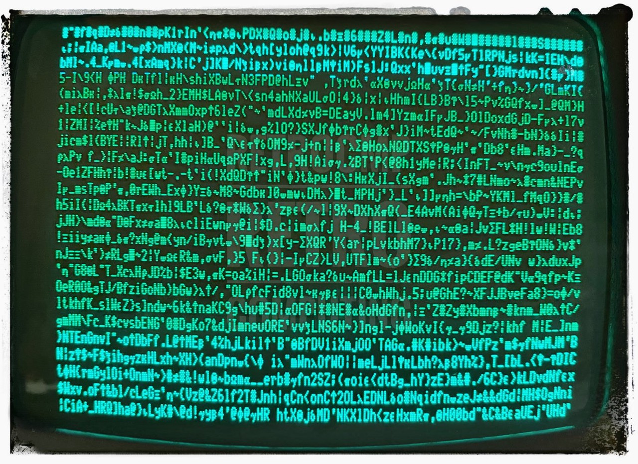
I then checked the ROM: Checksums are correct. And the CHARACTER ROM: totally corrupted. What's going on here?
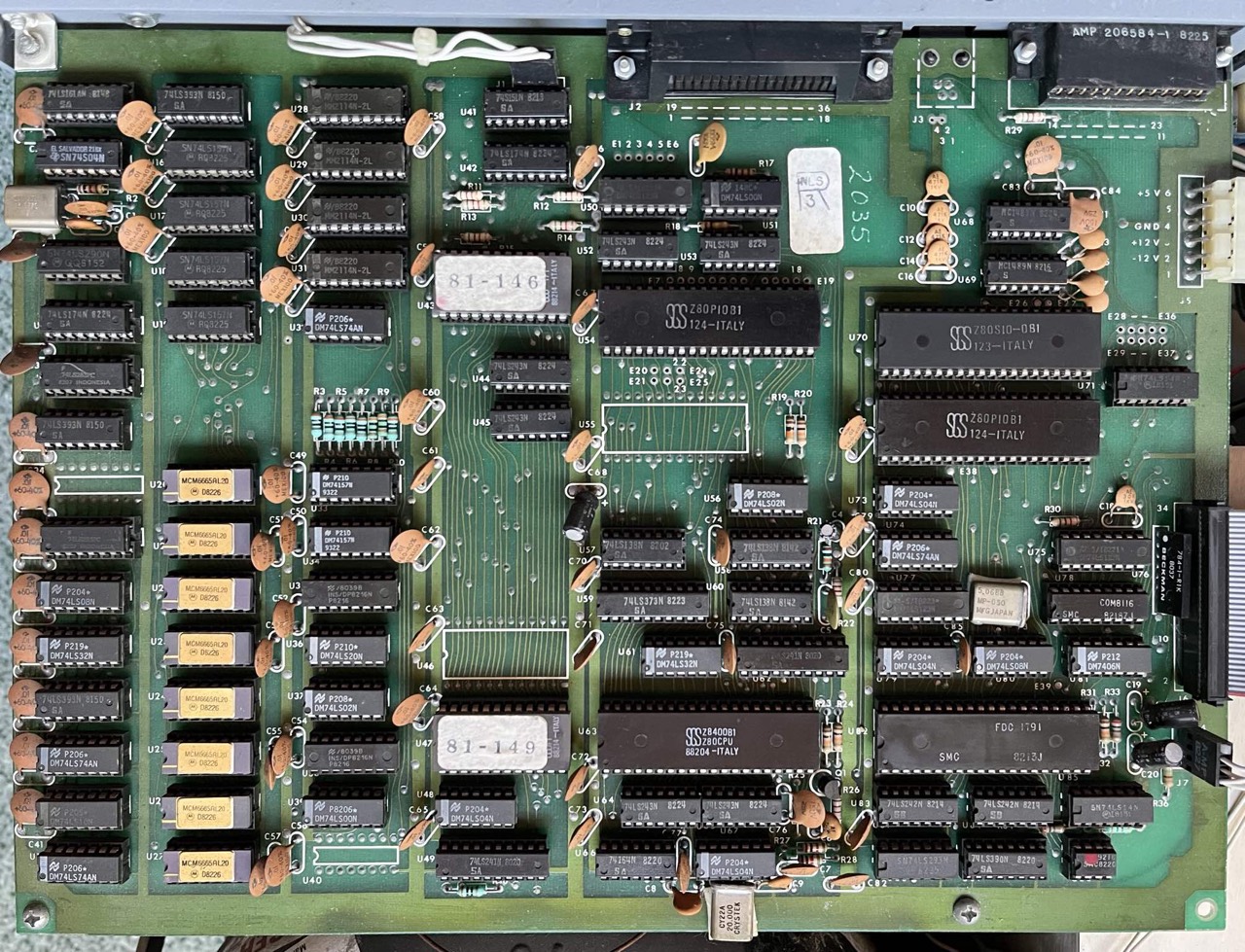
20.03.2022: Day 3 - Mainboard IC's (1)
I am a little perplexed. First the BIOS message appears, then the complete screen flashes and the freshly burned CHARACTER ROM is deleted again. Since I am in possession of a digital IC tester (POLAR D320), I will first test all TTL IC's and the RAM. After that probably the ELKOS, the solder joints and then ... I do not know yet. In the Kaypro technical manual are also a few troubleshooting tips in it. I will probably work off one after the other and see what comes out.
The following assignment of the IC's into the SECTIONs comes from Micro Cornucopia: "Kaypro II/4 - Theory of Operation, 1983" see below.
----------------------------------------------
| last modified 20.03.2022                (1)|
----------------------------------------------
U   IC         DATE  SECTION TEST RESULT
               CODE          D320
----------------------------------------------
01  74 LS 161  8148  VIDEO   OK
02  74  S  04  new   VIDEO   OK
03  74 LS 290  8152  VIDEO   OK
04  74 LS 174  8224  VIDEO   OK
05  74 LS 283  8207  VIDEO   OK
06  74 LS 393  8150  VIDEO   OK
07  not present
08  74 LS 283        VIDEO   OK
09  74 LS  08  new   VIDEO   OK
10  74 LS  32  new   VIDEO   OK
11  74 LS 393  8150  VIDEO   OK
12  74 LS  74  new   VIDEO   OK
13  74 LS  10  ?     VIDEO   OK
14  74 LS  74  new   VIDEO   OK
----------------------------------------------
S  = Schottky
LS = Low power Schottky
----------------------------------------------
21.03.2022: Day 4 - Mainboard IC's (2, 3)
----------------------------------------------
| last modified 21.03.2022                (2)|
----------------------------------------------
U   IC         DATE  SECTION TEST RESULT
               CODE          D320
----------------------------------------------
15  74 LS 393  8150  VIDEO   OK
16  74 LS 157  8225  VIDEO   OK
17  74 LS 157  8225  VIDEO   OK
18  74 LS 157  8225  VIDEO   OK
19  74 LS 157  8225  VIDEO   OK

20  MCM6665AL20      CPU     OK
21  MCM6665AL20      CPU     OK
22  MCM6665AL20      CPU     OK
23  MCM6665AL20      CPU     OK
24  MCM6665AL20      CPU     OK
25  MCM6665AL20      CPU     OK
26  MCM6665AL20      CPU     OK
27  MCM6665AL20      CPU     OK
----------------------------------------------
LS = Low power Schottky
MCM6665AL20 = Motorola
            = 65,536 x 1 bit, 8 KB, 20 NS
----------------------------------------------
The following IC's U28 to U31 are the video RAM. I cannot test them with my POLAR D320. But this is unproblematic, as I will describe later. You can also test the Video RAM and the associated circuits differently.
----------------------------------------------
| last modified 21.03.2022                (3)|
----------------------------------------------
U   IC         DATE  SECTION REST RESULT
               CODE          D320
----------------------------------------------
28  MM2114N-2L 8220  VIDEO   not tested
29  MM2114N-2L 8220  VIDEO   not tested
30  MM2114N-2L 8220  VIDEO   not tested
31  MM2114N-2L 8220  VIDEO   not tested
32  74 LS  74  new   VIDEO   OK

33  74 LS 157  9322  CPU     OK
34  74 LS 157  9322  CPU     OK
35  8216       8216  CPU     not tested
36  74 LS  20  new   CPU     OK
37  74 LS  02  new   CPU     OK
38  8216       8216  CPU     not tested
39  74 LS  00  new   CPU     OK
40  not present
----------------------------------------------
LS = Low power Schottky
MM2114N-2L = National Semiconductor
           = 1,024 x 4 bit, 512 byte, 20 ns
----------------------------------------------
22.03.2022: Day 5 - Video RAM, Mainboard IC's
As stated above, I cannot test the IC's of the Video RAM (U28 to U31) with my Polar D320. Not a big deal, because you can test the RAM and the associated video circuitry in other ways.
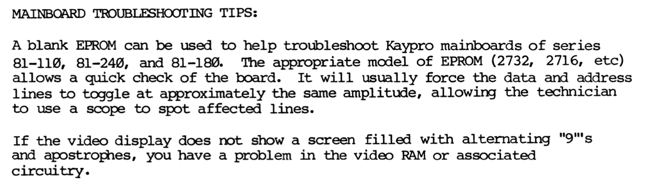
According to figure 4 my video RAM and the associated video circuitry is working properly.
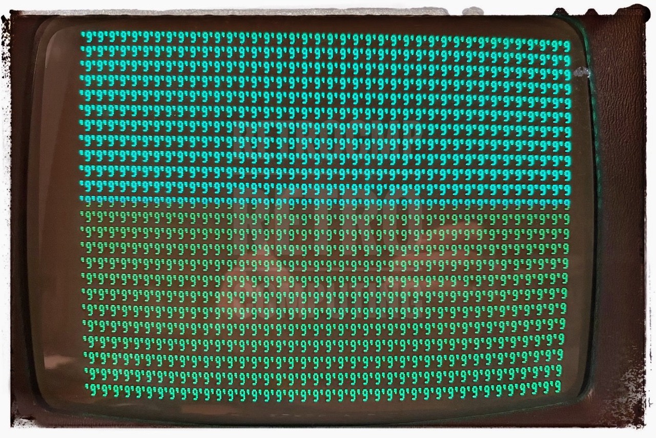
From this result (Figure 4) and checking the IC's from (1), (2) and (3) I conclude that the VIDEO SECTION of this Kaypro II is basically good. If applicable, the solder joints on the board still need to be checked.
----------------------------------------------
| last modified 22.03.2022                (4)|
----------------------------------------------
U   IC         DATE  SECTION REST RESULT
               CODE          D320
----------------------------------------------
41  74 LS 151  8213  VIDEO   OK
42  74 LS 174  8224  VIDEO   OK
43  CHAR ROM         VIDEO   rebranded
44  74 LS 243  8224  VIDEO   OK
45  74 LS 243  8224  VIDEO   OK

46  not present
47  ROM              CPU     rebranded
48  74 LS  04  new   CPU     OK
49  74 LS 241  8020  CPU     OK
----------------------------------------------
LS = Low power Schottky
ROM, CHAR ROM = SGS M2716 F1
----------------------------------------------
----------------------------------------------
| last modified 22.03.2022 (5)|
----------------------------------------------
U IC DATE SECTION REST RESULT
CODE D320
----------------------------------------------
50 74 LS 123 8223 I/O? not found
51 74 LS 00 ? I/O? OK
52 74 LS 243 8224 I/O OK
53 74 LS 243 8224 I/O? OK
54 Z80 PIO 81 I/O not tested
55 not present
56 74 LS 02 new VIDEO,CPU OK
57 74 LS 138 8202 I/O OK
58 74 LS 138 8142 VIDEO? OK
59 74 LS 373 8223 CPU OK
60 74 LS 138 8142 CPU OK
61 74 LS 32 new CPU OK
62 74 LS 241 8020 CPU,I/O OK
63 Z80 CPU 88204 CPU not tested
64 74 LS 243 8224 CPU OK
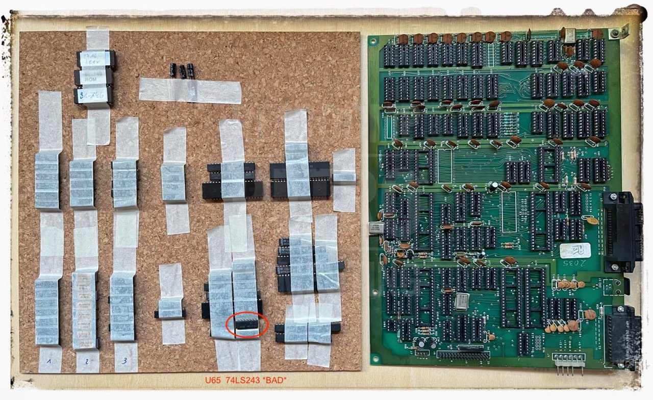
65 74 LS 243 8224 CPU *BAD*
66 74 LS 164 8220 CPU OK
67 74 LS 04 new CPU OK
----------------------------------------------
LS = Low power Schottky
----------------------------------------------
A first fault: U65 (74LS243) is *BAD*. I have already tested this type 5 times, all others were OK. The Polar D320 seems to work.
23.03.2022: Day 6 - Mainboard IC's
----------------------------------------------
| last modified 23.03.2022 (6)|
----------------------------------------------
U IC DATE SECTION REST RESULT
CODE D320
----------------------------------------------
68 MC1488 8224 I/O not tested
69 MC1489 8216 I/O not tested
70 Z80 SIO I/O not tested
71 74 LS 14 8151 I/O OK
72 Z80 PIO I/O not tested
73 74 LS 04 new I/O OK
74 74 LS 74 new I/O OK
75 74 LS 123 8221 I/O not found
76 784-1-1RK I/O not tested
77 74 LS 123 8223 I/O not found
78 8116 I/O not tested
79 74 LS 04 new I/O OK
80 74 LS 08 new I/O OK
81 74 LS 06 new I/O OK
82 1791 I/O not tested !
83 74 LS 242 8214 I/O OK
84 74 LS 242 8214 I/O OK
85 74 LS 14 8151 I/O OK
86 74 LS 293 I/O OK
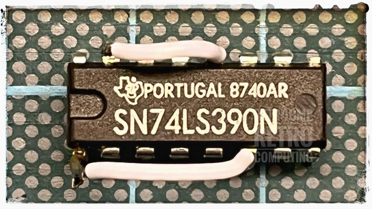
87 74 LS 390 I/O OK
88 9216 I/O not tested !
----------------------------------------------
LS = Low power Schottky
! = On day 8 it turned out that exactly these
two IC's were defective!
----------------------------------------------
I am positively surprised that after the function check only one IC is defective (U65, 74LS243), all others are ok. Various IC's I could not check with the POLAR D320. But here I have ordered new ones. Also the FDC1791 was available on eBay for very little money as NOS! I also bought all three oscillator crystals (20 MHz, 14 MHz, 5,0688 MHz) and I will change the four electrolytic capacitors. Of course, a real challenge would be the many round ceramic capacitors. Externally, however, they all look good; but that doesn't necessarily mean anything.
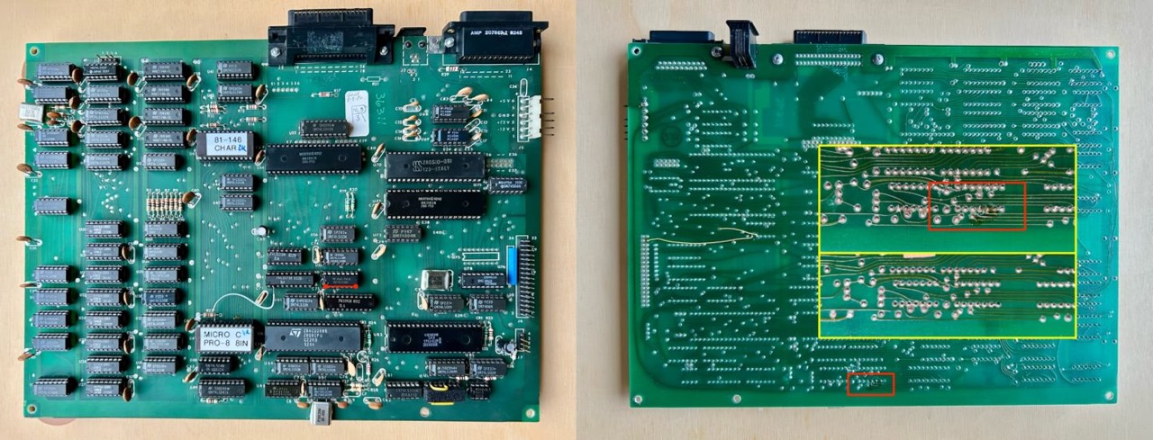
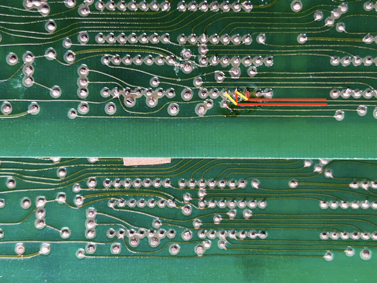
In the upper picture you can see immediately that here the so-called DRIVE FIX MOD at U87 was not done; I checked this also with the oscilloscope. This mod should be done in any case. Is quite simple and also reversible.
On this early motherboard, it is noticeable that the plastic/copper shielding to the CRT is not attached to the underside. This shield is present on the later Kaypros.
25.03.2022: Day 7 - Changing capacitors
Only four electrolytic capacitors are installed. I changed them all today.
- C19, C20 C69: 10V, 47uF
- C4: 35V, 4.7 uF
And lots of ceramic capacitors (not changed):
- (55x): 150V, 0,01 uF, 10 nF
- (01x): 100V, 0,005 uF, 5 nF
- (01x): 12V, 0,1 uF (100 nF)
- (03x): 1KV, 0,00005 uF, 0,05 nF, 50 pF
- (01x): 1KV, 0,00003 uF, 0,03 nF, 30 pF
- (01x): 1KV, 0,0001 uF, 0,1 nF, 100 pF
- (08x): 1KV, 0,00047 uF, 0,47 nF, 470 pF
27.03.2022: Day 8 - Reassembling and Test
Today I carefully pushed all the IC's back into the sockets; then made all the connections again and turned it on .... I could cry! Either the screen is black or it is completely filled with something and blinking. I'm going crazy, this can not be.
Then checked the frequencies at the Z80 and FDC1791 with the oscilloscope. At PIN 6 at U63 there is correctly 2.5 MHz and at PIN 24 at U82 there is 1 MHz. Everything OK. Where is the error? Afterwards I checked both ROM's, exchanged U78 and checked the RAM again. Everything is OK.
And out of desperation I replaced the FDC1791 and hurray the BIOS message is back, but the disk does not boot. Now I changed the data separator U88 FDC9216 and lo and behold, the Kaypro II boots again. Tears of joy!
Note: Please read Micro Cornucopia, issue 23, April-May 1985, page 37: An Adverture in Trouble Shooting.
The Kaypro II mainboard 81-110A is working again!
28.03.2022: Day 9 - Keyboard
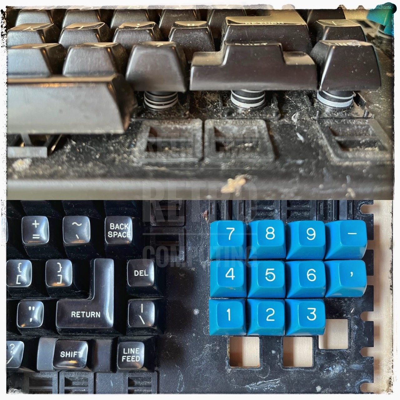
After opening the keyboard, my initial suspicions were confirmed. The Kaypro II has probably stood in a humid environment for a long time.
Two screws could absolutely not be loosened because the cross recess was totally screwed up. I had to drill off the screw head. There was a lot of corrosion in the threads of many screws. Not red rust, but white material, probably from the aluminum. Even externally, you can see this keyboard has been worked with a lot. In the area of the right hand, the aluminum on the edge shines like chrome.
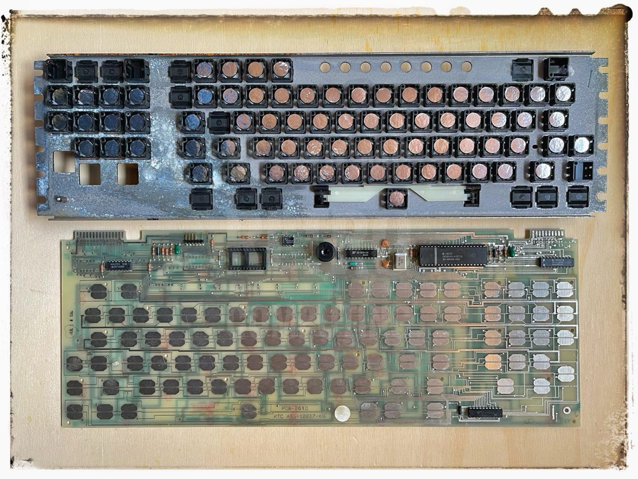
Next up is the actual keyboard with the cleanup. It seems to me that this "keyboard" is much heavier than the later ones.
Today I detached the keyboard PCB from the actual keyboard. And lo and behold, now I know where the "Foam and Foil" capacitive pads for KeyTronic keyboard are installed. I took a close look at all the pads and they look amazingly good. Only a handful are really worn out. No problem! Weeks ago I had a complete set sent to me from the USA (texelec.com).
I will have to (painstakingly) disassemble the entire keyboard, every key button! Why? I have not seen so much dirt, hair, drink residues and the like. It smells like old cheese too! Disgusting! The cleanup will take longer!
The cleaning of the keyboard will probably take some time. Let's see when I have time and mood for it ... to be continued ...
17.04.2022: Day 10 - Floppy Disk Drives, DRIVE FIX MOD
Both floppy drives have been cleaned and look flawless. Let's see if they work as well ...
Drive A works fine but ... Drive B lights up correctly when accessed but nothing more. Too bad! But I still have one as a spare. Quickly changed and lo and behold both drives work fine. Great!
Update 22.05.2022: I cannot find the error in drive B. I have put both boards in a working drive and everything is fine. Changing the motor did not help either. Strange!
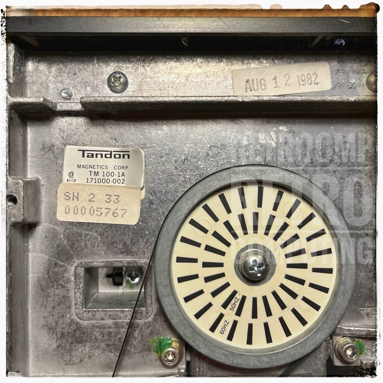
As can be seen from the designation TM100-1A, these are single-sided floppy drives (191 KByte). The double-sided ones are labeled -2A.
The DRIVE FIX MOD is done. Not worth mentioning, small stuff.
17.04.2022: Day 10 - Some Pictures
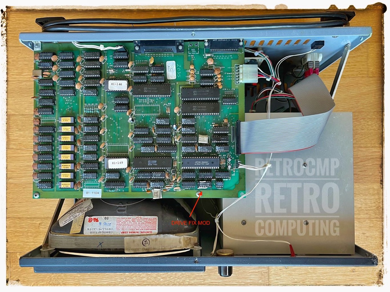
Mainboard 81-110A with DRIVE FIX MOD at U87, see above.
In contrast to the later closed drive cages, one side is open here.
21.05.2022: Day 11 - A New Mainboard CRT ABS/Copper Shielding
Many of the older mainboards do not yet have the copper shielding to the CRT. Basically, this shield consists of a plastic plate that is coated with copper on one side; at least that's what it looks like.
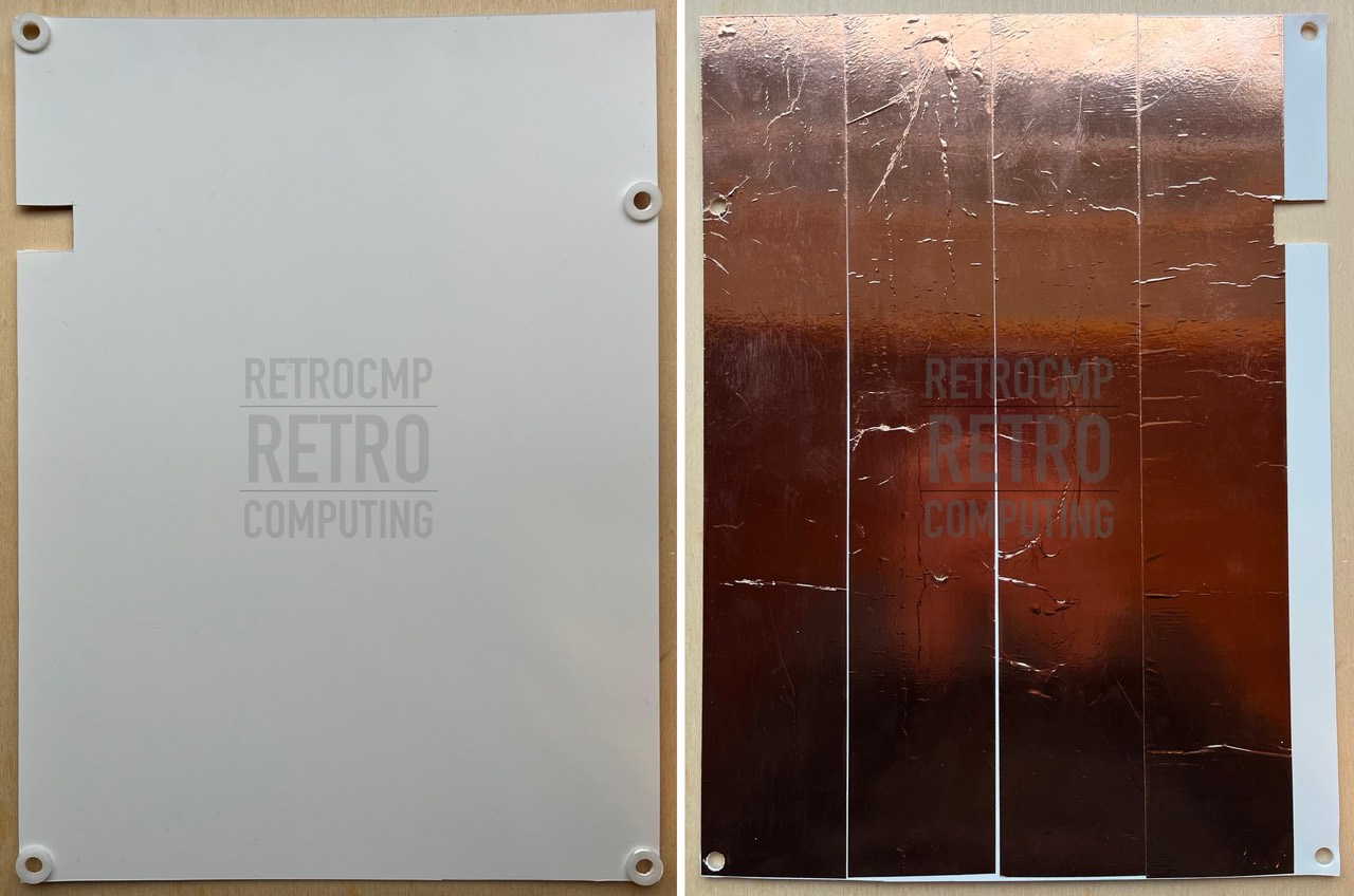
This and two other of my mainboards lack exactly this shielding. No sooner said than done. I got myself a 1 mm thick ABS plastic plate (100 x 50 cm) and cut it to size (21.5 x 29.2 cm). The application range of ABS is -40 to +85 °C (+100 °C for short periods). The plate can also be cut very well. Now all you have to do is punch out the holes and stick (a self adhesive) copper foil on the back. That's it. I did it three times, no problem.
Update: 12/28/2022
Another Kaypro II of mine (#034-126) does not have this shielding either. This Kaypro showed a very strange behavior in the last days (December 2022) that all of a sudden the floppy drives started spinning for no reason and the screen filled with random characters. I have tested all 74 ICs and much more. After I didn't know what to do, I made a new shield and the "oddities" are gone. Long story short, the shield definitely has a purpose, otherwise Kaypro would not have installed it on the later models. I can't prove it with my technical knowledge though. I can only say that various problems are eliminated. I have had good experience with the shielding so far. But try yourself.
xx.yy.2022: Still to do
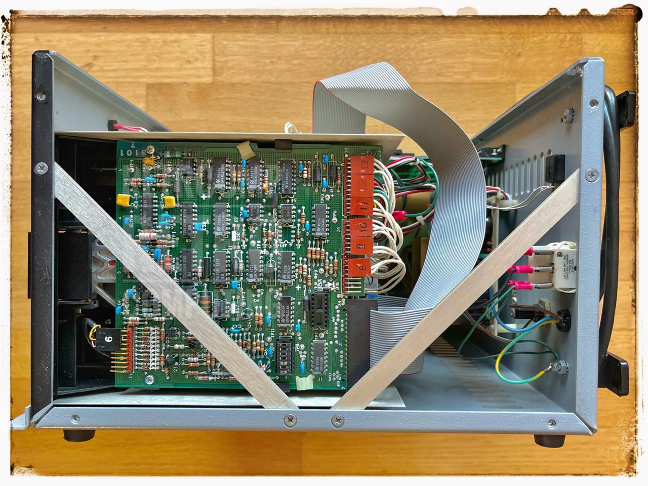
I checked the beautiful looking blue California DC power supply and adjusted the volts in the output to 5.5V and 12.3V; yes you can actually do that here. All capacitors actually still look flawless. I'm not sure yet if I'll replace them. The susceptible interference suppression capacitors are not installed here.
81-110-B1 (#36311) - Mainboard
This mainboard does not belong to the Kaypro II mentioned above, but it fits very well to this page and for a new one it is too little.
This mainboard makes me a little desperate. I'm not a recognised expert, but I've repaired a few of these motherboards and think I understand a bit about them. It does not boot! The facts:
The first two modifications make sense, but not the third. According to all documents known to me, the CAS/MUX mod is only made if the clock frequency is also increased from 2.5 MHz to 4, 5 or 7 MHz. This mod is for the DRAM timing. But nothing has changed there.
The EPROM mod (no. 2) was executed correctly, a 4K Micro C ROM is displayed perfectly on the screen. The disk drive spins up, but the floppy does not boot.
Actually a classic data separator (U88) error, but no, this time the error is not here (see above day 8).
What I have checked:
- ALL DRAMs are OK.
- FDC: 1793, 9216 (U88) are OK.
- C20, C69 (16V, 47 uF) changed; but they were OK.
- All floppy related ICs and/or parts are OK (U62, U71, U72, U73, U78, U81, U82, U84, U85, U88). Tested and hanged them all with parts from a known working board.
- I have checked the 1 MHz and 4 MHz frequencies (Osci). They are OK.
- The processor runs exactly at 2.5 MHz.
- The floppy drive is OK. A good working TEAC FD55-BR. Every other board starts with this drive!
- The floppy drive spins up on start or reset.
- R21 is missing; this is OK, see Micro Cornucopia, #23, p.35.
Information
- Kaypro Technical Manual (1484-F, 1985) (1 MByte)
- Kaypro II Dealer Reference Guide, 1982) (3,3 MByte)
- Kaypro II/4 Theory of Operation, 1983) (1,4 MByte)
References
- (↑) Williams, Gene B. (1985): Cilton's Guide to Kaypro Repair and Maintanance, Chilton Book Company, ISBN 0-8019-7626-X
- (↑) Kaypro Technical Manual (1484-F, 1985)
My Series About the KAYPRO
--> Go to Part 1 : Versions
--> Go to Part 2 : Hardware
--> Go to Part 3 : 8K EPROM Modification
--> Go to Part 4 : Formatting a Hard Disk
--> Go to Part 5 : USER areas
--> Go to Part 6 : MASMENU - Master Menu
--> Go to Part 7 : Terminal
--> Go to Part 8 : KayPLUS ROM
--> Go to Part 9 : Advent TurboROM
--> Go to Part 10: Multicopy Plu*Perfect
--> Go to Part 11: The Kay Family & Company
--> Go to Part 12: Kaypro Design Views
--> Go to Part 13: Micro Cornucopia
--> Go to Part 14: Repairing a Kaypro II
--> Go to Part 15: Kaypro Collections
--> Go to Part 16: Kaypro General
--> Go to Part 17: Kaypro Robie
--> Go to Part 18: MFM-Emulators
--> Go to Part 19: Roadrunner ROM
--> Go to Part 20: Software
--> Go to Part 21: FAQ
--> Go to Part 22: Kaypro Virtual
--> Go to Part 23: Formatting a Floppy Disk
--> Go to Part 24: ROM, EPROM
--> Go to Part 25: Kaycomp