Firmware Programming
I don't want to say much about the Gotek and the FlashFloppy upgrade. Take a look at Keir Fraser's page on Github and the Facebook (group) and you will find all the information you need.
Flashing the Gotek
Note: In 2021, Gotek has changed the microcontroller for availability and price reasons. The new ones are now from Artery (AT32F415, AT32F435), with the F435 being more powerful. The flashing workflow has therefore also changed.
Artery
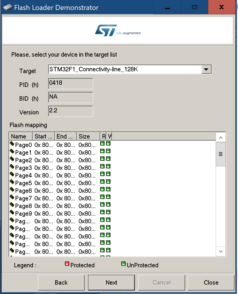
STM32F105
Old serial workflow! New Gotek's with the STM32 microcontroller are no longer available (since 2021)!
At this point, I would just like to describe my workflow for the actual 1st flashing. Why? I spent at least three or more hours of trial and error yesterday and today because in 99% of the cases the STM32 bootloader did not have access to the Gotek. But then suddenly everything worked perfectly. The next time I tried it, it didn't work again. I almost went crazy. Even the instructions with the Gotek reset did not bring any success.
But then, by chance, I discovered the following workflow for myself. This workflow is only necessary with a new, unflashed Gotek. Once FlashFloppy is on the Gotek, future updates can be installed directly via the USB interface.
I use an USB to serial adapter (FTDI, FT232RL, UART) on my iMac with Parallels Desktop and Windows 10. And yes, the two important lines RX and TX are connected correctly, i.e. reversed on the Gotek! So far, so good.
Important note: You can only follow the instructions below if you are familiar with the basic flashing procedure. Be sure to read the Github Wiki! Also, the Gotek must be modified for flashing.
For operation the Gotek needs only the 5V and the GND line.
Handling instructions:
- Connect the Serial/USB adater with Windows 10.
- Connect GND to Gotek and set the programming mode (jumper).
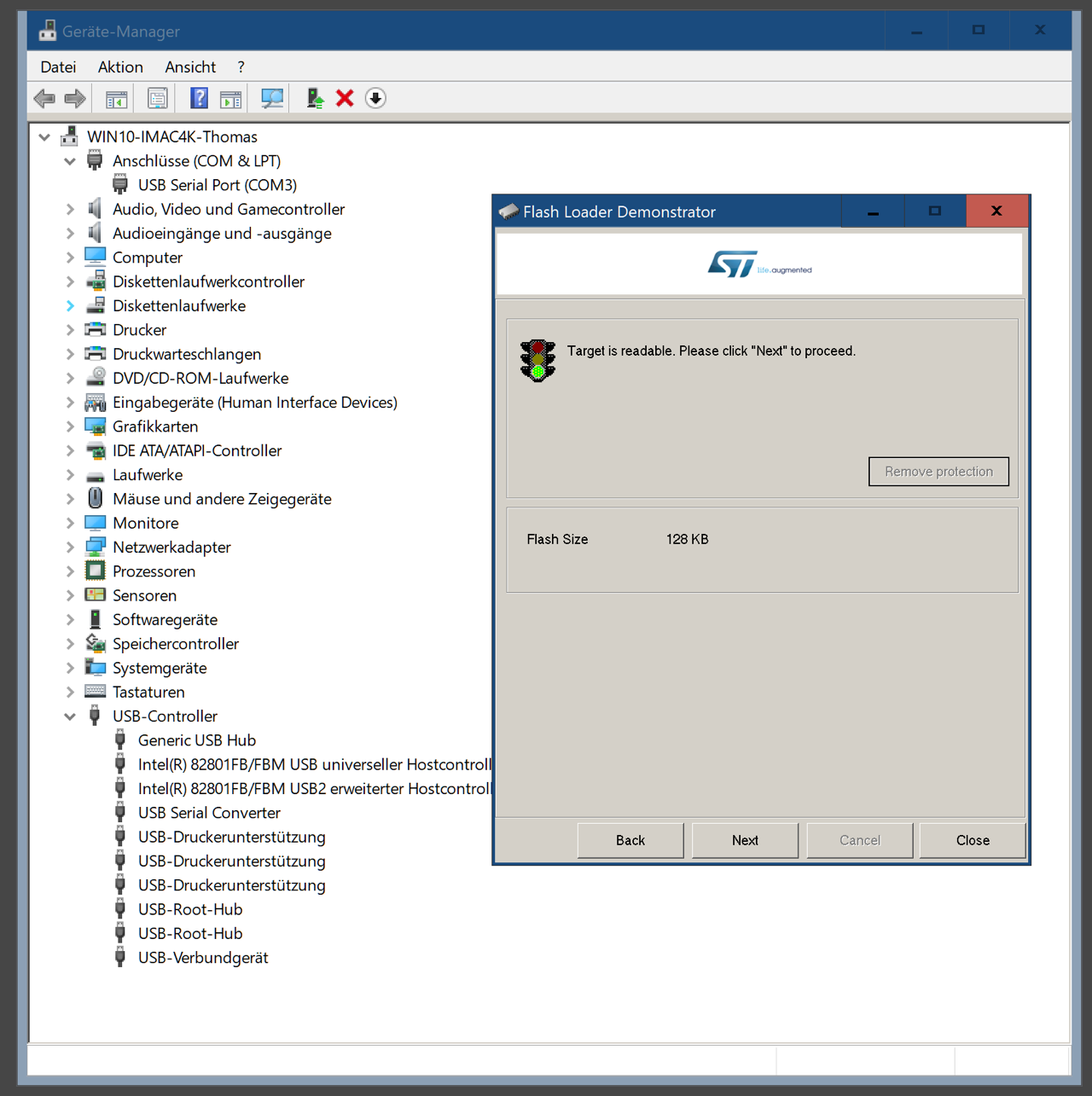
- Check the Windows „Device manager“ for the correct COM settings (115200, 8, EVEN, 1, N).
- Start the STM Microelectronics GUI and check for the correct COM settings.
- Connect 5V to Gotek.
- Connect RX/TX Serial/USB to TX/RX Gotek.
- Click on „Next".
- Now a new screen should immediately appear with a green signal light and the note: „Target is readable". If not, too bad. ¯\_(ツ)_/¯
Steps (5) and (6) should be carried out quickly one after the other!


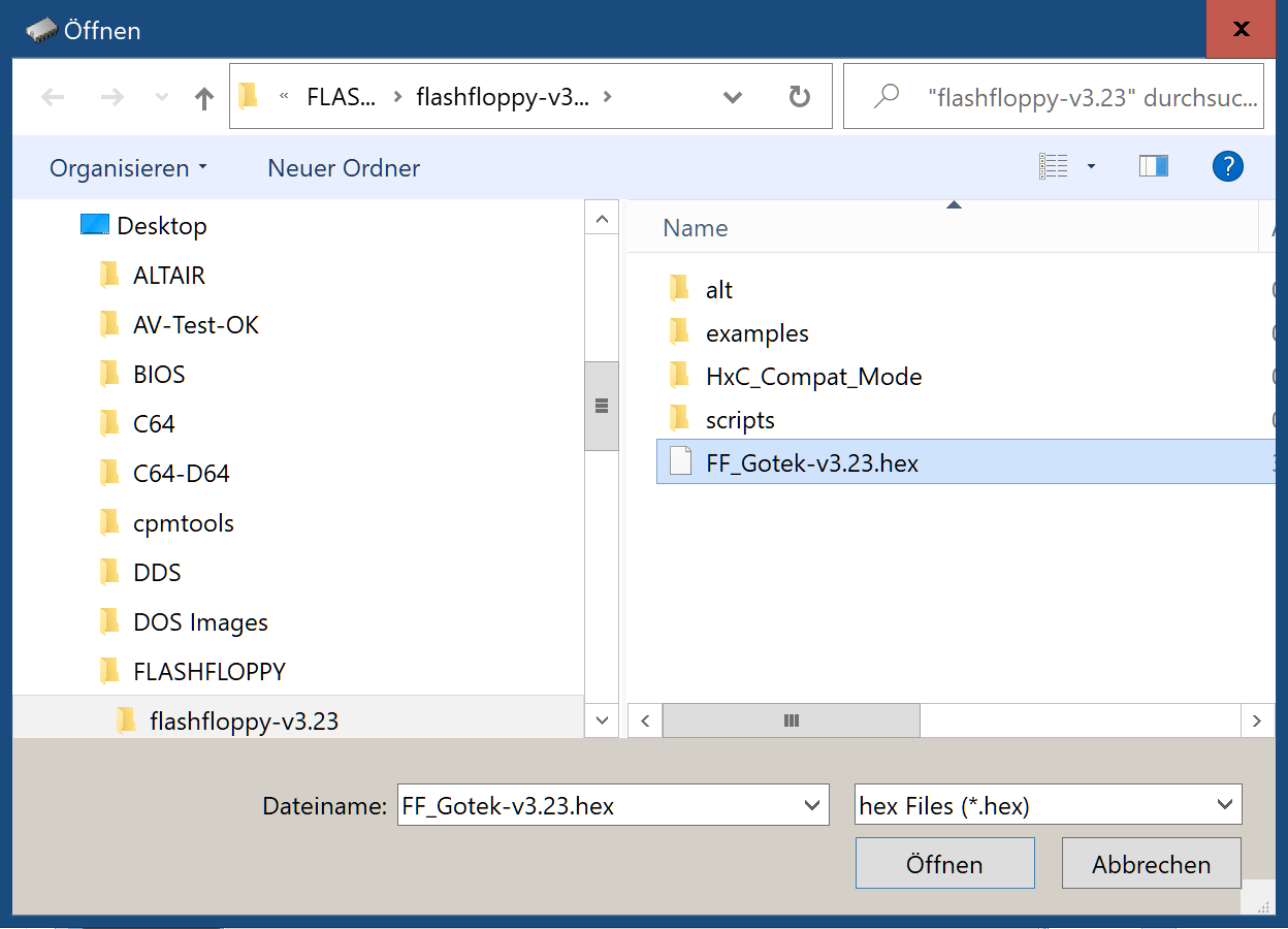
-> Steps (5), (6) and (7)

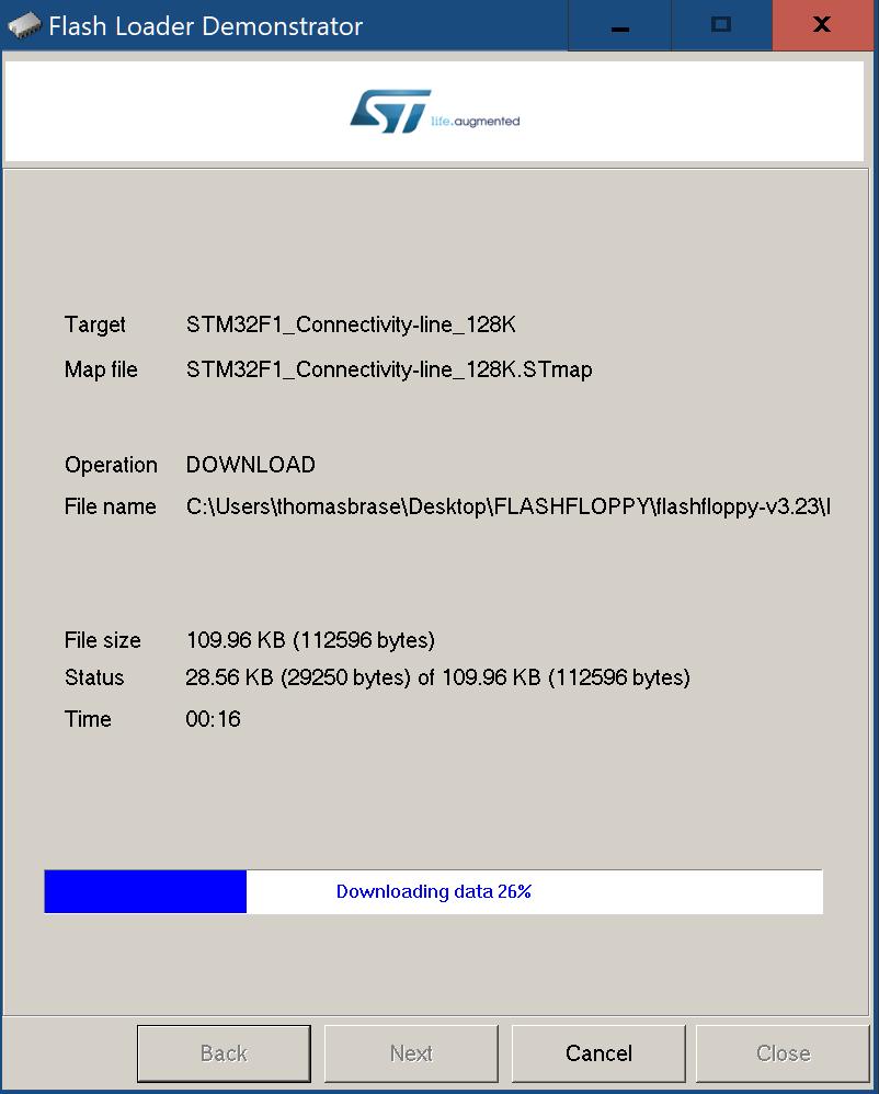
Done!
Hardware Mods
Following Keir Frazer's instructions, I added an OLED display (128x32: 0.91", 2.23") and a piezo speaker after installing FlashFloppy. The OLED display has the advantage that you can also read the currently active image with the file name.

Only the replacement of the display is a bit tedious because it has different dimensions and does not fit without manual modifications; precisely aligned and fixed with hot glue.
Before that, however, I had to scrape off the existing plastic ridges with a wide soldering iron. If it is not too hot, this works perfectly and without stench. The plastic can then be cut like butter!
Documents
Data Sheets
- Future Technology Devices International Ltd.: FT232R USB UART IC
Links
- (keirf) Github: FlashFloppy a floppy drive emulator for Gotek hardware
- YouTube: Gotek drive - Flash Floppy custom firmware install and ...