<-- Back to Part 0: Information
--> Go to Part 2: Hard-Sectored Disks
I EXPLICITLY WARN YOU THAT YOU MAY PERMANENTLY DESTROY YOUR HARDWARE IF YOU MAKE ANY TECHNICAL CHANGES TO IT. I DO NOT ACCEPT ANY RESPONSIBILITY OR LIABILITY WHATSOEVER IF YOU CARRY OUT MODIFICATIONS TO YOUR HARDWARE ON THE BASIS OF MY PERSONAL TECHNICAL DOCUMENTATION. IF YOU MAKE ANY MODIFICATIONS TO YOUR HARDWARE, YOU DO SO AT YOUR OWN RISK. ALWAYS ENSURE THAT THE PLUG CONNECTIONS ARE CORRECTLY SEATED. EVEN TOUCHING SENSITIVE COMPONENTS SUCH AS CPU, RAM, ... CAN CAUSE THEM TO BE IRREVOCABLY DESTROYED (ELECTROSTATIC DISCHARGE - ESD). WITH MANY OLD COMPUTER POWER SUPPLIES, VOLTAGE IS STILL APPLIED TO COMPONENTS EVEN WHEN THE SWITCH IS IN THE OFF POSITION.
!!! WARNING !!!
Many thanks to Mike Douglas (DeRamp.com) for his assistance in getting my North Star Horizon up and running!
Restoration
- Purchase
- Disassembly
- S-100 Boards
- PSU, Capacitors
- Floppy Disk Drives
- Cooling Fan
- Parallel Port
- Terminal
- CP/M
- Alive!
- Downloads
- Information
- References
Purchase
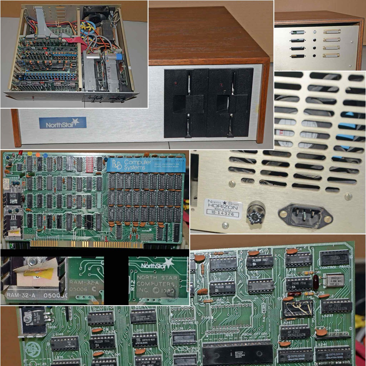
No. 1: North Star Horizon (S/N 14-326)
My dream was always an Altair Mits 8800 but the prices are beyond good and evil. And since a favorite topic of mine are floppy drives and I am also able to read and write hard-sectored floppy disks, the North Star Horizon was an obvious choice. The prices are still reasonable.
Another reason for the North Star is the good availability of scanned manuals and a lot of software images (NSI); there are at least a hundred NSIs on the internet. No wishes remain unfulfilled here.
Furthermore, there are at least two people who have documented the restoration of a North Star Horizon very well on the Internet. And so I bought (end of January 2023) a North Star Horizon (S/N 014-326) on the internet. I am very curious.
I've been very familiar with the Kaypro (~03/1982) since last year, but the Horizon goes another five years further back in time (~11/1977). I have already made contact with someone who knows this computer very well: Mike Douglas (DeRamp.com). Another cornucopia of information is of course available in the VCF Forum (S-100).

(with a later front site logo)
Journey
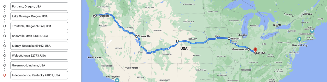
23. Jan 2023 22:30 PST
Tracking Details Uploaded
PORTLAND, OR

24. Jan 2023 0:01 PST
In Transit - In FedEx possession
LAKE OSWEGO, OR 97035

24. Jan 2023 15:07 PST
In Transit - Left FedEx origin facility
PORTLAND, OR 97217

25. Jan 2023 18:08 PST
In Transit - Delay - Package delayed
TROUTDALE, OR 97060

26. Jan 2023 6:13 PST
In Transit - In transit
SNOWVILLE, UT 84336

26. Jan 2023 18:22 PST
In Transit - In transit
SIDNEY, NE 69162

27. Jan 2023 6:24 PST
In Transit - In transit
WALCOTT, IA 52773

28. Jan 2023 9:48 PST
In Transit - Departed FedEx location
GREENWOOD, IN 46143

30. Jan 2023 7:36 PST
In Transit - In transit
INDEPENDENCE, KY 41051

30. Jan 2023 18:32 PST
Arrived at the Global Shipping Center
Erlanger, KY 41025

31. Jan 2023 20:17 PST
Shipped from the Global Shipping Center
Erlanger, Kentucky 41025-2501

2. Feb 2023 2:06 PST
In Transit with Destination Carrier
Leipzig, XX 410252501

2. Feb 2023 7:38 PST
In Transit with Destination Carrier
Hannover, XX 410252501

2. Feb 2023 15:12 MESZ
Delivery
Sarstedt, NDS, Germany
Today on 02/02/2023 the North Star Horizon - perfectly packed - arrived at my home; nothing loose, no rattling. A total of 11 days from Portland, USA to Sarstedt, Germany. The world has become small.

No. 2: North Star Horizon (S/N 18-916)
Disassembly
Today on 02/03/2023 I first disassembled and cleaned the North Star Horizon (no 1). But it was not very dirty.
Cabinet

I use SUPER CLEAN for cleaning PCBs. Stuck fine dust can be removed wonderfully with it.

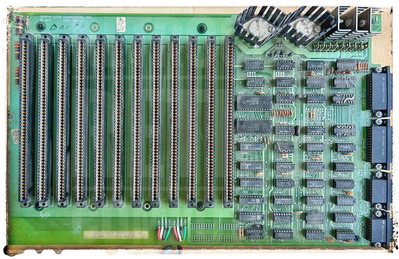
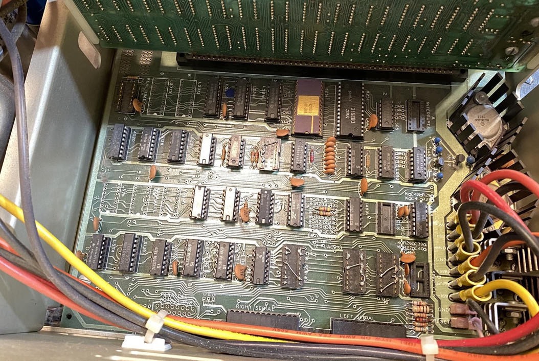
Mainboard
No. 1: North Star Horizon (S/N 14-326)
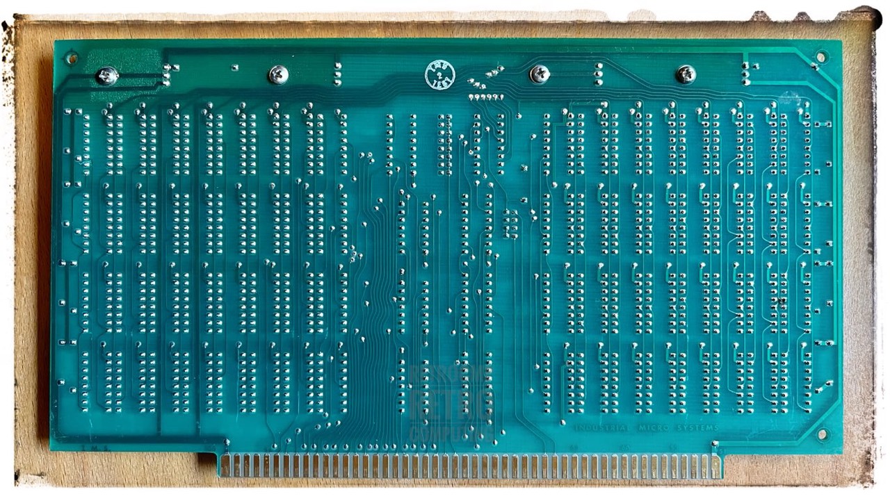
It was only by chance that I found out that some S-100 slots do not work properly. I didn't notice anything during the normal visual test. I found this out when I tested my various RAM boards. I have both 4 x 8K IMS and 4 x 16K DRC. Sometimes all board series worked perfectly and sometimes not. I found out about the faulty slots by simply changing the cards. So, if a board is supposedly not working, it can also be due to a slot. But there are no shorts!

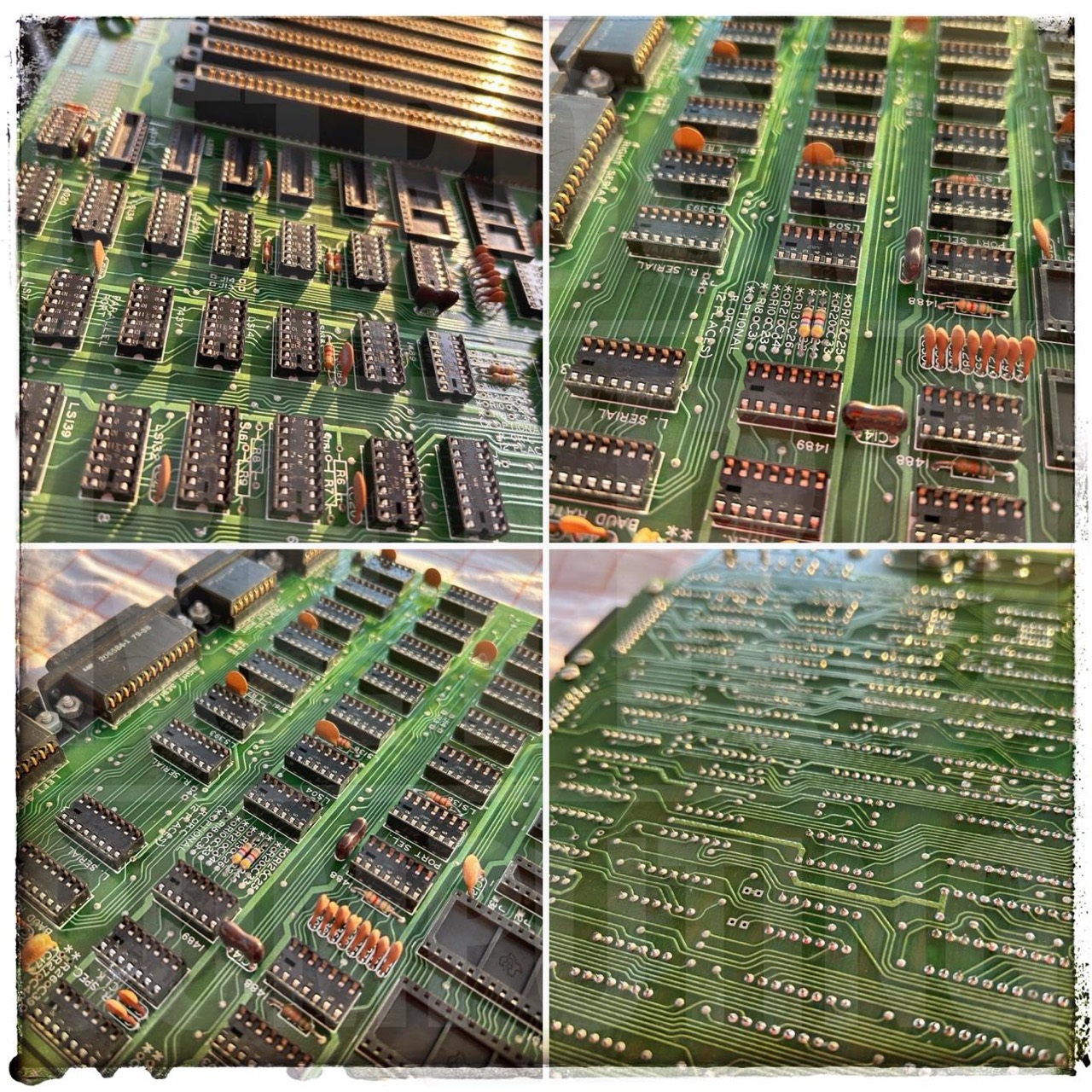
First I tested all 74*** ICs: all OK. Most ICs are date coded 79; the oldest is a 74LS132N from 7913; upper left.
Curiously, a 1488 (1B) and a 1489 (1C) were missing. In all boards known to me (pictures from the Internet) both are always equipped.
Noticeable features
The center 5V voltage regulator (7805) and heatsink were replaced sometime in the past. This can be seen from the solder joints and the "different colored" heatsink. From the bottom side of the board you can also clearly see a faint brown coloration (heat effect).
No. 2: North Star Horizon (S/N 18-916)
This is my 2nd Horizon. But since I don't want to create a separate page for it, you can find my descriptions here.
First I tested all 74*** ICs: all OK. Most ICs are date coded 79; the oldest is (also) a 74LS132N from 7838; same place as above.
The motherboard of my 2nd North Star Horizon is really dirty. When I disassembled it (02/26/2023), I just took a quick look. But also like my first one, the middle 5V regulator on the mainboard has been replaced before; probably due to heat issues.
A closer look (03/11/2023) at the backside showed that the -16V trace got several damages. Nearly the complete conductor path is burned through. I had to repair the hole trace.
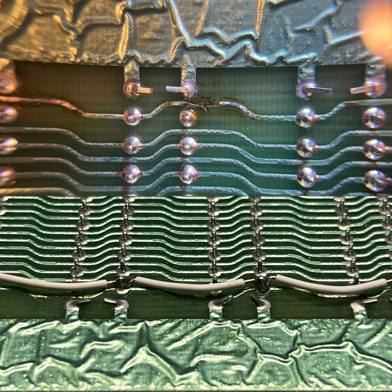
I can't say how many amps are flowing through each of the 16V lines on the motherboard. However, if you look at the +16V on the front and the -16V on the back, you will immediately notice that the wire gauges differ by classes of size.
For the repair I used a single core AWG 24 copper cable. This can be loaded with max. 3.5 amps. This should be enough: 16V x 3.5A = 56W
The problem of the burnt out -16V trace is also often mentioned: here is an example. This problem seems to occur whenever a tantalum capacitor on the -volt rail breaks.
See below: Reducing the input voltage.
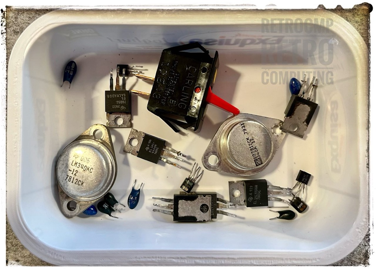
Furthermore I replaced the entire power supply section; all regulators and all capacitors; some formerly blue capacitors were almost black. The toggle switch (reset) was also faulty.
Update 04/25/2023: Actually, I thought that this mainboard was in perfect order, but alas, not so. By chance, I came across three faulty S-100 slots during my test of the IMSAI RAM-4A. Now, in retrospect, I can also explain the strange behaviour of other RAM boards. I cannot yet say where exactly the error is. I would have to remove the mainboard first. But the RAM-4A definitely works incorrectly on three slots, while it runs perfectly on all the others. And I was already almost despairing. Now then, another lesson learned.
No. 3: North Star Horizon (S/N unknown)
I only mention this motherboard because it was very dusty, but the dust could not be removed with a brush. The board simply remained matt and dull. So I carefully removed all the ICs and washed the board in the dishwasher at 40 degrees Celsius for an hour. I then blew out all the water and displaced the residual moisture with isopropanol. Finally, I dried it with a hot air gun using a lukewarm air stream. Result. It looks like new and shines in the sun. Unfortunately, you can't see the fine dust very clearly in the first picture.
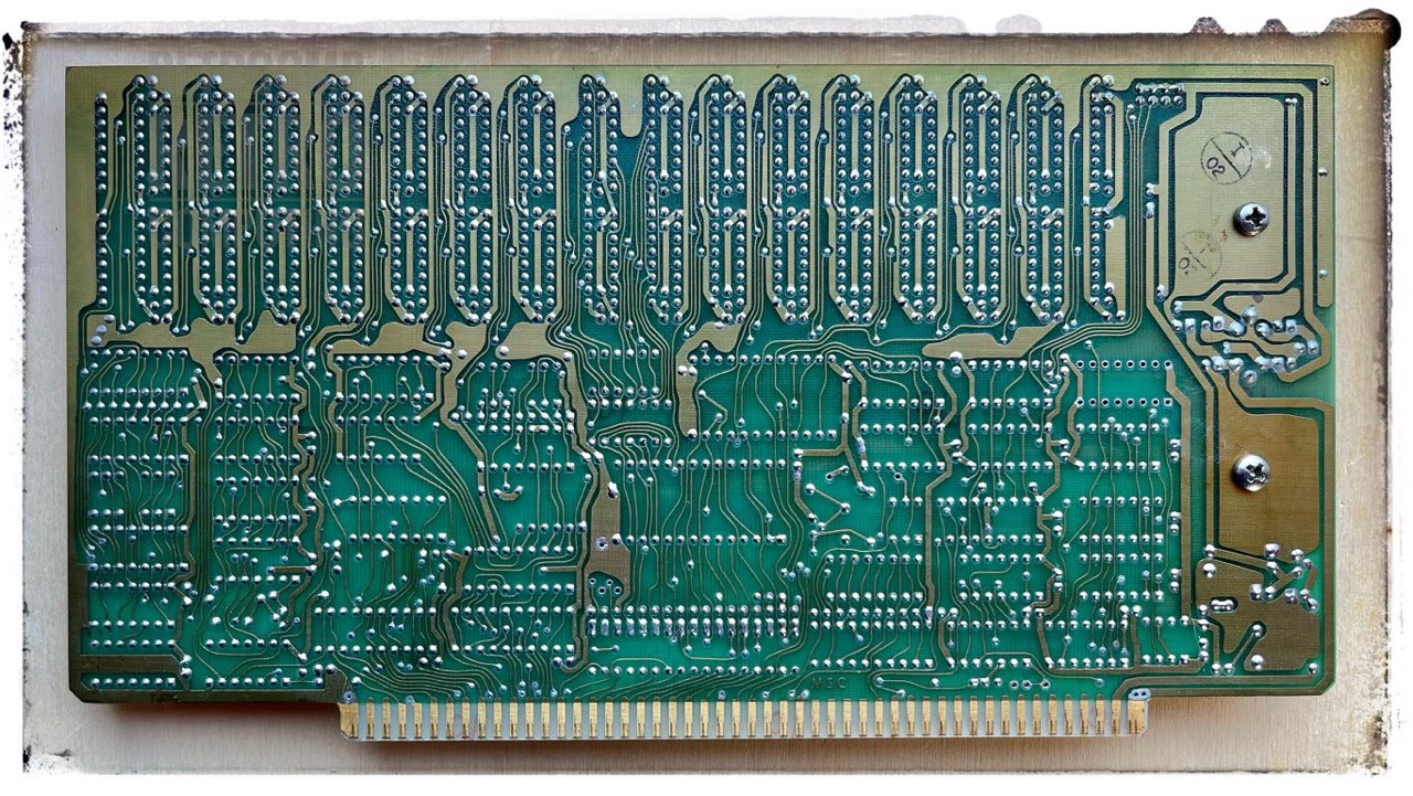
My S-100 Boards
Below you will find all my S-100 boards that I (basically) use in my two Horizons.
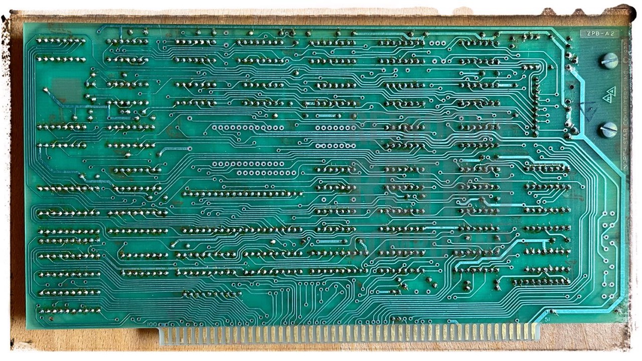
- CPU: N* ZPB-A2
- RAM: IMS RAM (8K)
- RAM: IMS RAM (16K)
- RAM: N* Ram-16-A (16K)
- RAM: DRC-16 (16K)
- RAM: Artec 32k-100 (32K)
- RAM: CompuPro Econoram X A (32K)
- RAM: N* RAM-32-A (mod 64K)
- RAM: N* HRAM-64 (64K)
- RAM: MSC DMB6400 (64K)
- RAM: CompuPro RAM17 (64K)
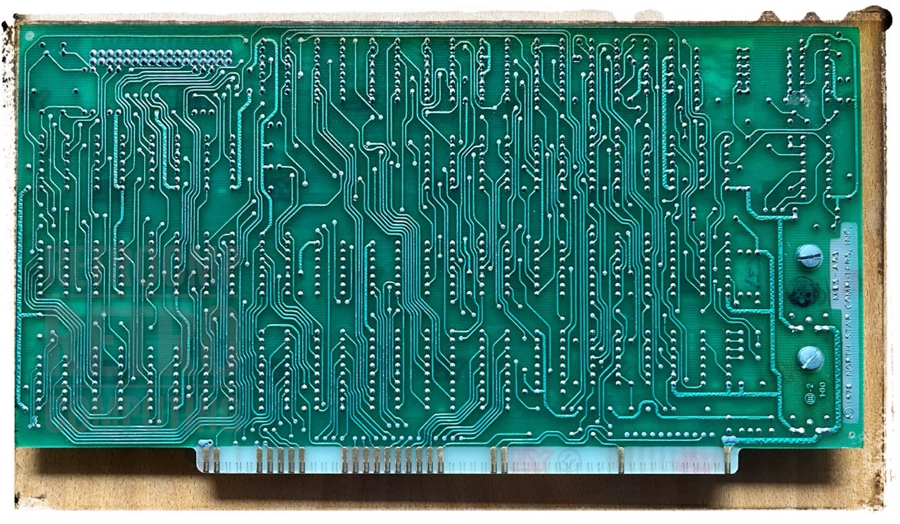
- FDC: N* MDS-AD
- FDC: N* MDS-AD3
- FDC: N* MDC-A4
- FDC: Morrow - DJDMA
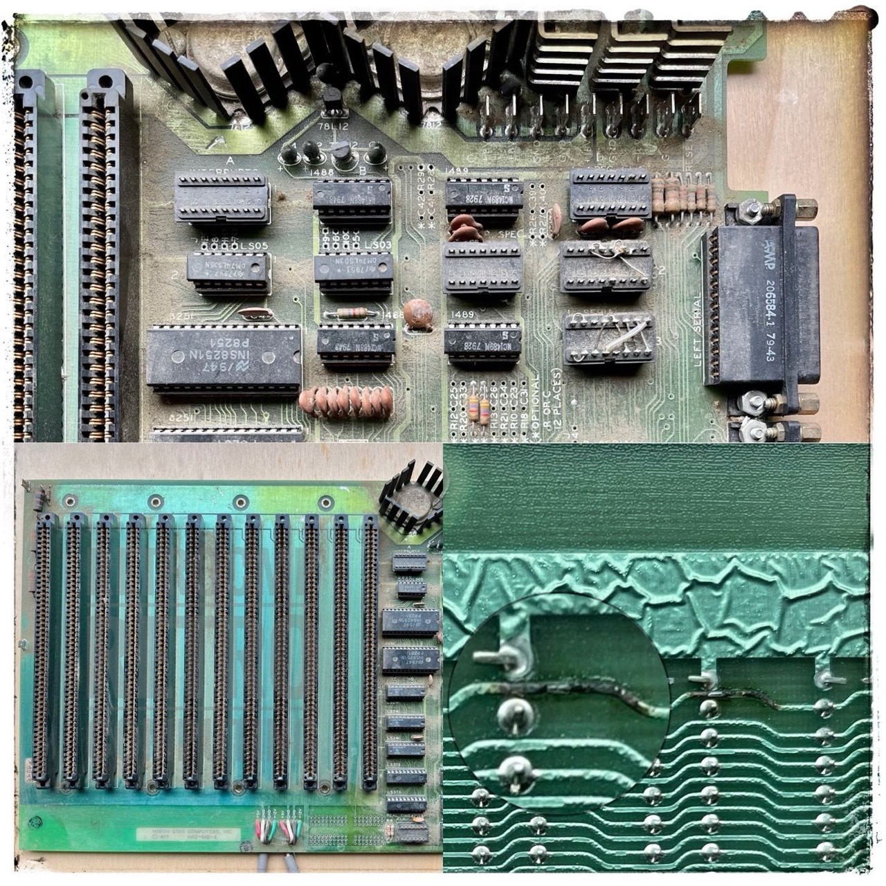
N* ZPB-A2 - Z80 Processor Board
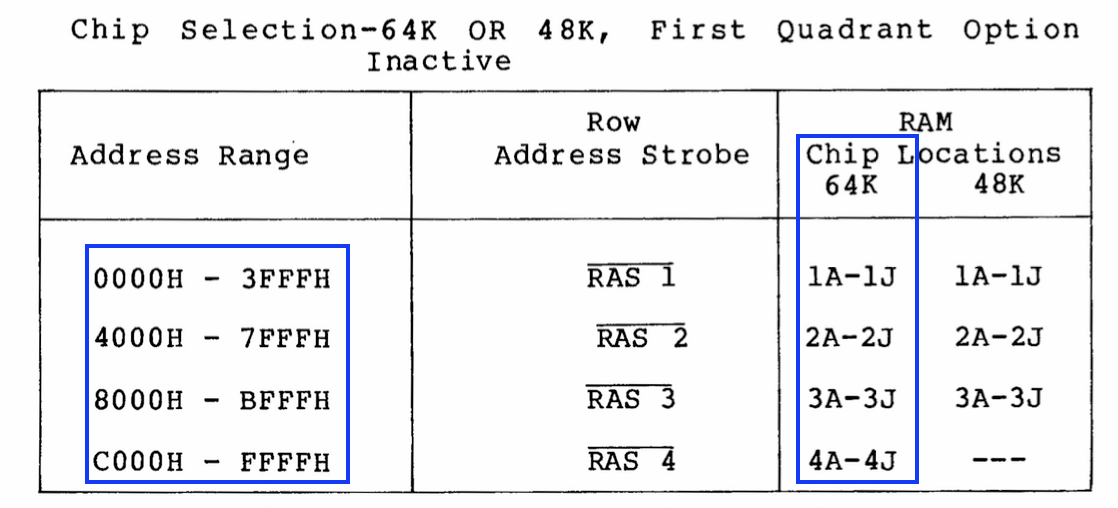
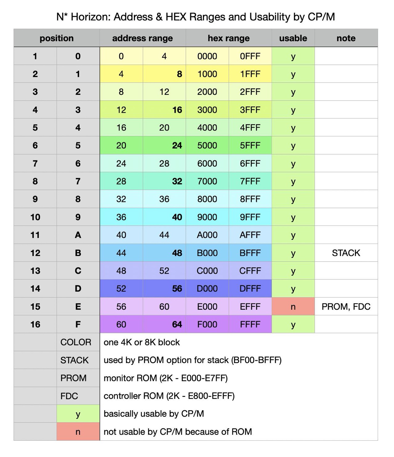
Without PROM option. But I will build this later on advice by Mike Douglas. The PROM on the CPU was typically placed at E000 and the micro disk controller occupies E800-EBFF. For this reason, the North Star also has a maximum of 56K RAM (0000-DFFF). The last 8K cannot be used as RAM. Unless you can still enable the memory in smaller blocks like on the HRAM-64.
First I tested all 74*** ICs: all OK. The oldest is a 74LS02N from 7712.

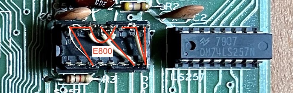
The floppy disk controller is located at address E800 by default.
Next you can see the minimum version of the ZPB-A2 board. No PROM option, no CONTROL PANEL option and no IC sockets. I have tested the lines of the three missing 74LS241 for continuity with the multimeter. And this is what came out.

Since Sep 2023 I have three ZPB-A2 CPU boards; two with PROM option and one with none.
PROM Option
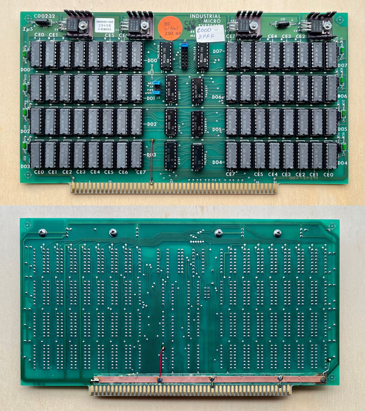
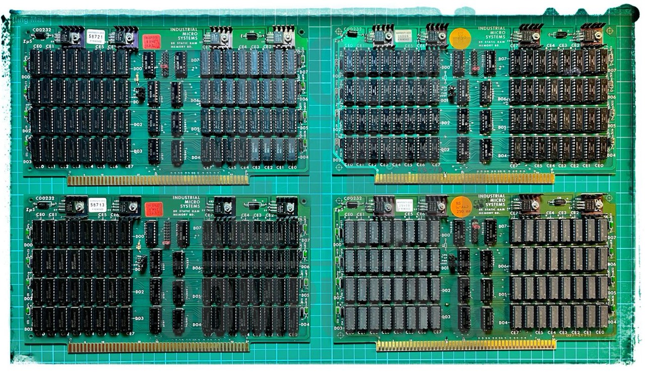
IMS - Static RAM - 8 KByte
This was an early non-IEEE 696 S-100 RAM board. As opposed to dynamic memories, the IMS did not require periodic RAM refreshing.
Currently (07/2023) I have four of these boards. They are one of my favourites.
This board is equipped with 2 x 32 MM2102AN-2L (1,024 x 1 bit, 200ns). According to the manual it is compatible with the Altair 8800 and IMSAI 8080; the PINs 20 and 70 are not grounded.
Jumper settings: PH = OFF, SP = ON, PWR = OFF, MWRT = ON.
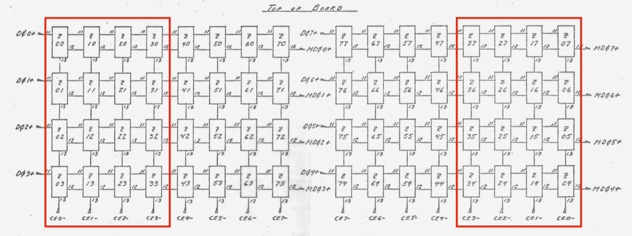
The 2102 or 21L02 RAM ICs used on the IMS 8K board are arranged as 1024 by 1 bits. Eight of these chips are "paralled" to drive a storage of 1024 8 bit words or bytes. There are eight of these groups on the board driving a total board storage capacity of 8192 (8K) 8 bit words. These eight 1K blocks can be referred to as eight 1K "pages" of RAM.
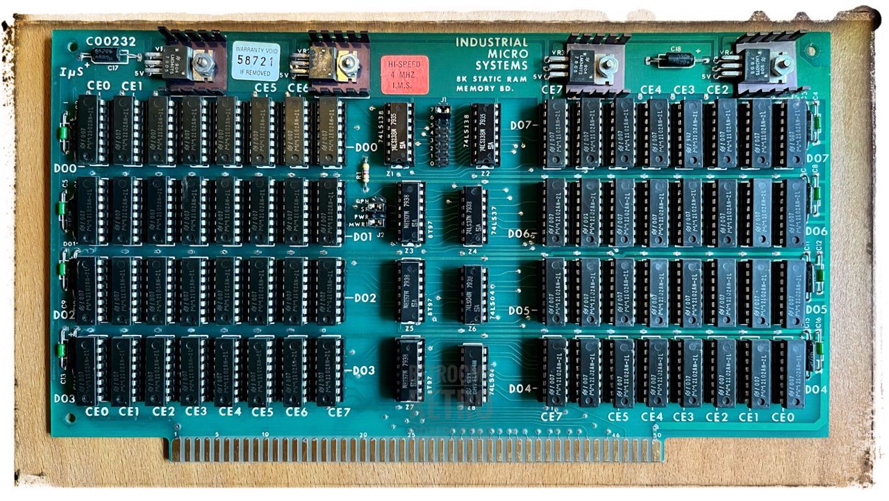
Next is the RAM IC calculation to find a bad IC. A RAM tester is not much use with these old boards, because you don't want to test all 64 because of one or two defective ICs.
Address range: A000 to BFFF, 8K
A000 - AFFF: 4K - 4 x 32 ICs
B000 - BFFF: 4K - 4 x 32 ICs

---------------------------------------
A000 - A3FF / CE0 / Z00 - Z07

bit 0       / Z00
bit 1       / Z01
bit 2       / Z02
bit 3       / Z03
bit 4       / Z04
bit 5       / Z05
bit 6       / Z06
bit 7       / Z07
---------------------------------------
A400 - A7FF / CE1 / Z10 - Z17

bit 0       / Z10
bit 1       / Z11
bit 2       / Z12
bit 3       / Z13
bit 4       / Z14
bit 5       / Z15
bit 6       / Z16
bit 7       / Z17
---------------------------------------
A800 - ABFF / CE2 / Z20 - Z27

bit 0       / Z20
bit 1       / Z21
bit 2       / Z22
bit 3       / Z23
bit 4       / Z24
bit 5       / Z25
bit 6       / Z26
bit 7       / Z27
---------------------------------------
AC00 - AFFF / CE3 / Z30 - Z37

bit 0       / Z30
bit 1       / Z31
bit 2       / Z32
bit 3       / Z33
bit 4       / Z34
bit 5       / Z35
bit 6       / Z36
bit 7       / Z37
---------------------------------------
B000 - B3FF / CE4 / Z40 - Z47
...

1) board #58721

Mon> TEST A800 A9FF
A9AF 7B 6B
           *
        7654 3210
     7B 0111 1011
     6B 0110 1011
           *
=> bit 4, CE2
=> the bad IC is Z24

Mon> TEST AB00 ABFF
AB7D D8 C8
           *
        7654 3210
     D8 1101 1000
     C8 1100 1000
           *
=> bit 4, CE2
=> the bad IC is Z24

2) board #58713

Mon> TEST A000 AFFF
A2CA ED FD
           *
        7654 3210
     ED 1110 1101
     FD 1111 1101
           *
=> bit 4, CE0
=> the bad IC is Z04

A801 A7 A3
              *
        7654 3210
     A7 1010 0111
     A3 1010 0011
              *
=> bit 2, CE2
=> the bad IC is Z22

---------------------------------------
Note: I made this calculation with
the help of Mike Douglas; Mar 2023
---------------------------------------
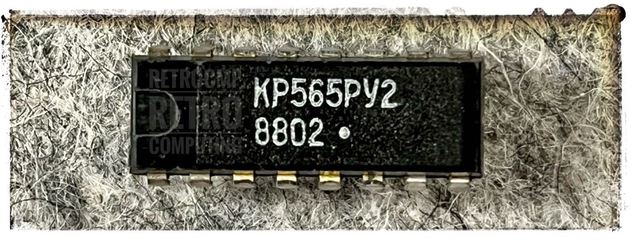
On a testing base I replaced three faulty MM2102AN-2L with Russian KR565RU2. These were a bargain at ebay (from Poland, 0,5 euro/pc); original MM2102AN-2L currently cost up to 4 EUR per unit at ebay Germany!
Yes, the attentive observer will of course now say that the access times are not identical. However, initial memory tests via the PROM Monitor did not show any errors. I also don't want to use the memory boards in permanent operation. They should only work for the time being.
Next you can see a modificated IMS-8K. This one can be used in IEEE 696 S-100 systems but no more in an IMSAI or Altair with a front panel. PIN 20, 53, 70 are grounded here.
I have completely reset the two modified boards so that I can use them later in the IMSAI 8080. Now I have four working boards (in total 32K). I do not need the IEEE 696 standard.
Hunger for Electricity
This is one of my favorite RAM boards (so far). I've never had any problems with it. It wasn't until my second IMSAI with my Signal 24-12 transformer that I accidentally realized how power hungry these old boards are. I had installed an Econoram XA (32K) and two IMS 8K and wondered why the voltage on the 8V line went down to 6.5-7.0V. After I replaced all the boards with a CompuPro RAM17, the voltage suddenly jumped up to 8.5V. Oops. In retrospect, this also explains why the rectifiers got so warm.
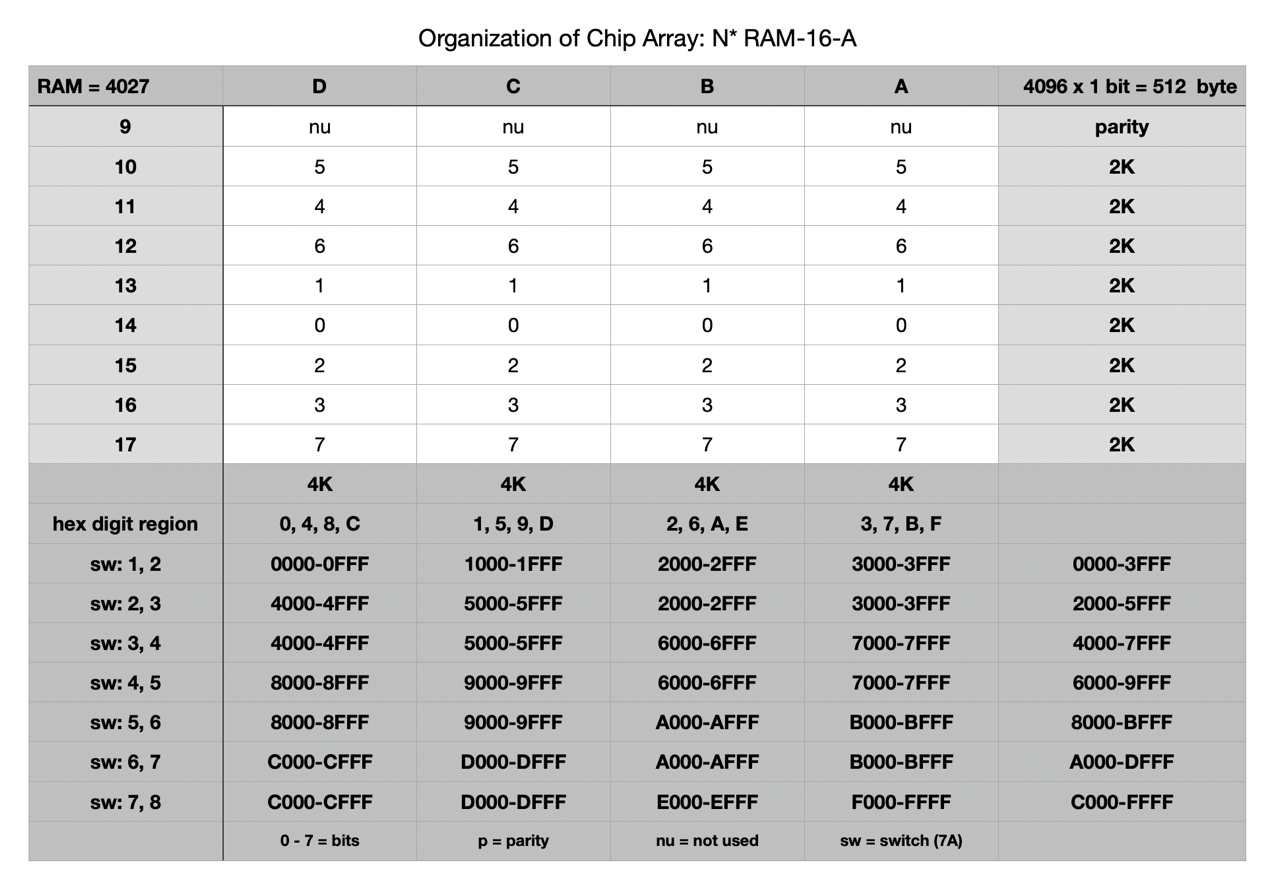
N* RAM-16-A - Dynamic RAM - 16K
This board is equipped with 4x8 ITT4027 3D (4,096 x 1 bit, 16 pin, date code 7846).
On the DIP header 7D below 1-2-3 and 6-7 are connected, here they soldered. This is the default setting on the N* Horizon when bank switching is not used.


The disadvantage of this memory card is that the IC RAMs of the type 4027 are hard to get and if they are, they cost a lot of money. A unit price of $4 or EUR 5 is not uncommon!
DRC-16 - Static RAM - 16K
This board (from about 1978) is equipped with 2 x 16 HM4721 14P-3 (1,024 x 4 bit, 18 pin). The board is divided into four 4K areas. You can put each area into each 4k boarder of the 64K range. The settings are very easy.

The 16K are organized in four 4K blocks A, B, C and D. Due to the simple but effective address allocation (see below left) you can allocate each 4K block freely in the 64K address range. On this DRC board all ICs are socketed and it even offers waitstates, phantom and bank select. The only thing that needs getting used to is the 4bit organization, well then.
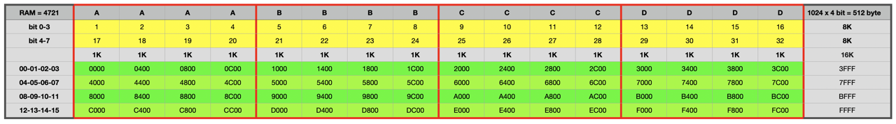
These boards are also among my favourites. I have enabled 16K on three boards and only 8K on the fourth. This gives me 56K for my Horizon. More is not possible there.
Artec 32K - Static RAM - 32K
This was an early non-IEEE 696 S-100 RAM board from about 1977. The PINs 20 and 70 are not grounded; therefore can be used in the IMSAI 8080 or Altair 8800.
This board is equipped with 8 x 8 TMS4044 25NL (4,048 x 1 bit, 18 pin). The settings are very easy. I plan to use this board in my IMSAI 8080. You can use this board in 2 MHz or 4 MHz systems. I have tested it in my N* Horizon (4 MHz), it works fine.
I actually only bought this board because it was offered on eBay Germany. Here, the S-100 community is not as strong as in the US. There I would have paid 2-3 times as much for it and then shipping and customs.
CompuPro Econoram X A - Static RAM - 32K
This board is equipped with 8 x 8 MM2147J (4,048 x 1 bit, 18 pin). According to the manual this board is compatible with the IEEE 696/S-100 standard. This can be recognised by the fact that the signal lines 15, 16, 17 are connected through (on the solder side). This board is from about 1979.
This board is organized as two blocks of 16K each: A + B. Each block can be set to start on any 4K boundary in the currently addressed 64K page. The corresponding bits are vertical organized: left is bit 0 and right is bit 7. Each row are 4K, beginning with A0 at the top (A0, A1, A2, A3, B0, B1, B2, B3).
The most important switch is S3 (right): RAM starting addresses. Here: Block A starts at 0K (0000), block B starts at 16K (4000).
Switch S1: all OFF. I do not use extended address selection. U12 (25LS2521) is removed!
Switch S2: all ON, but S2-1 and S2-3 OFF.
I actually only bought this board because it was offered on eBay Germany. Here, the S-100 community is not as strong as in the US. On ebay US this board was offered and sold in 2023 for $200. Shipping to Germany costs about $40 and customs including VAT also another $50. So all together about $300. I only paid 1/3! The Godboud S-100 boards are basically of very good quality. Therefore: Better have than need!
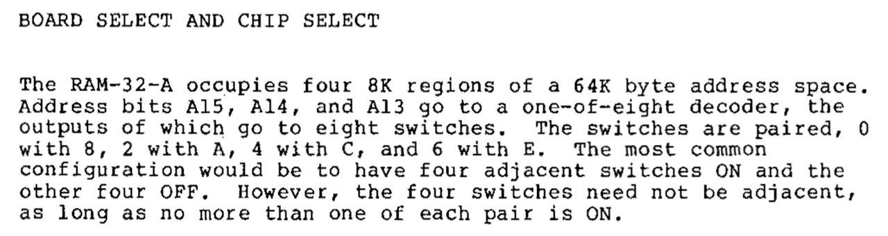
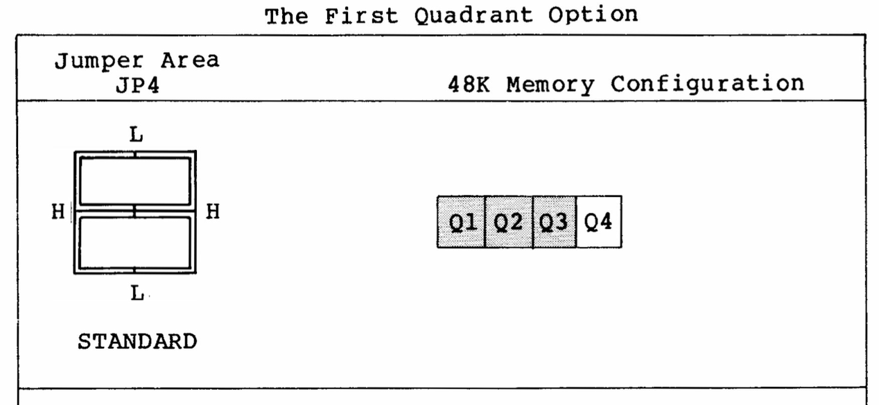
N* RAM-32-A - Dynamic RAM - upgraded to 64K
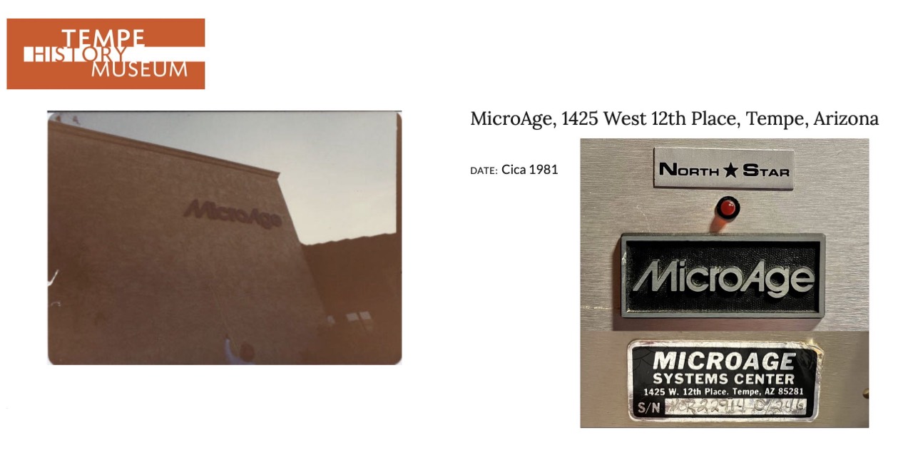
R&B Computer Systems seems to have been a larger company; it is mentioned, for example, in InfoWorld magazine, Dec. 31, 1980. I have removed the label from the RAM card.
The modification from 32K to 64K was a normal procedure at that time to upgrade an existing RAM card with little effort and cost and is described in detail by Steve Leibson in The Compass Newsletter, Vol 2, No 4, page 6. [12]
The disadvantage of this 32K RAM card was already at that time that the used 8K ICs were hard to get in case of failure and the just upcoming 16K ICs became cheaper. According to the manual, six different ICs could be used in the RAM-32-A, but they were not compatible with each other. All these reasons spoke for an upgrade to 64K already at that time.
Do not be confused by the DIP header 7D below. I have only 16p and no 14p headers. 1-2-3 and 6-7 are connected; 8 is a dead end.
Unfortunately all TTL IC's on the left side are without sockets. Errors can be found very difficult if something should be defective there.
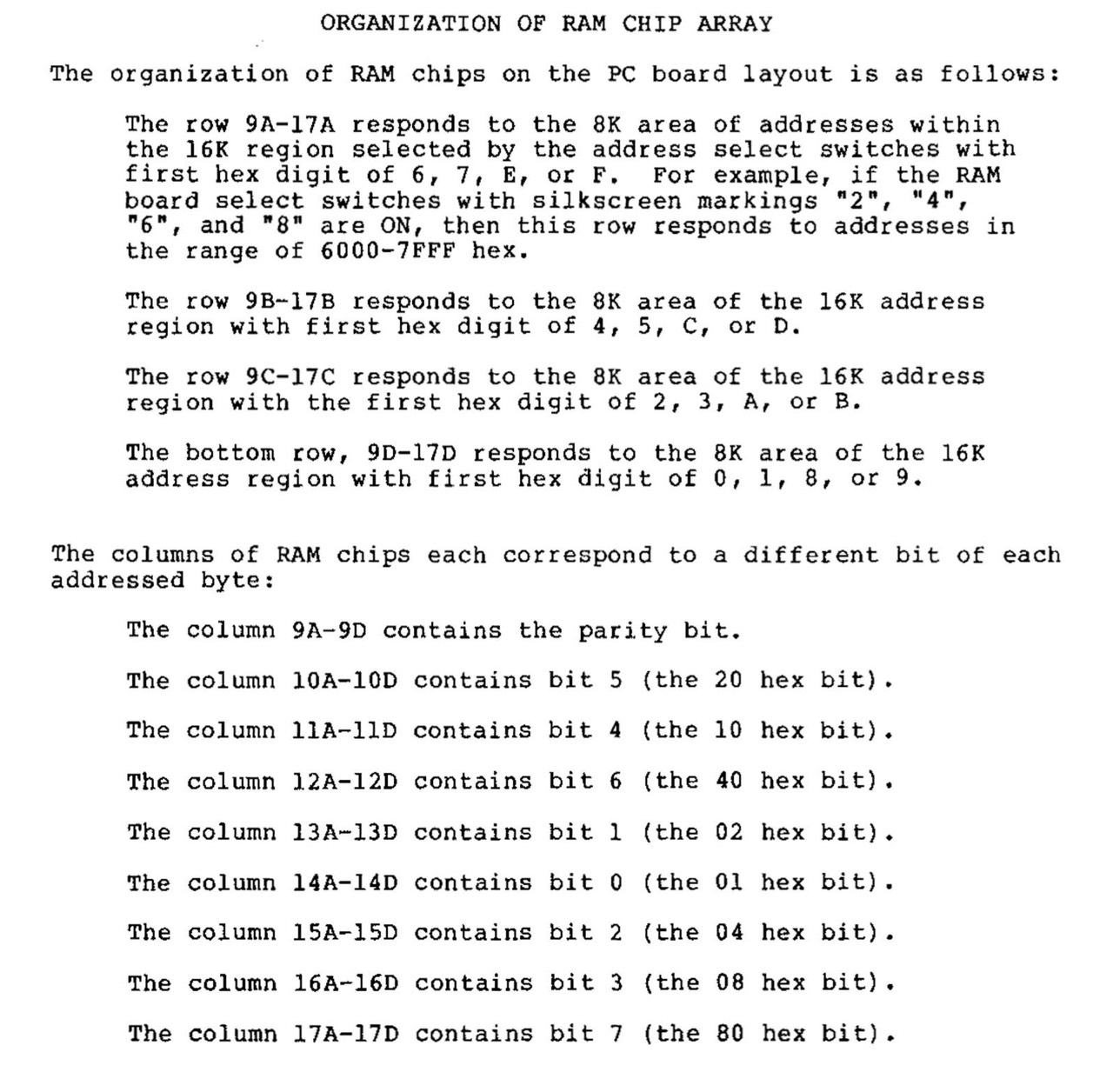
This board is equipped with 4 x (8+1) NEC upd416C (16,384 x 1 bit).

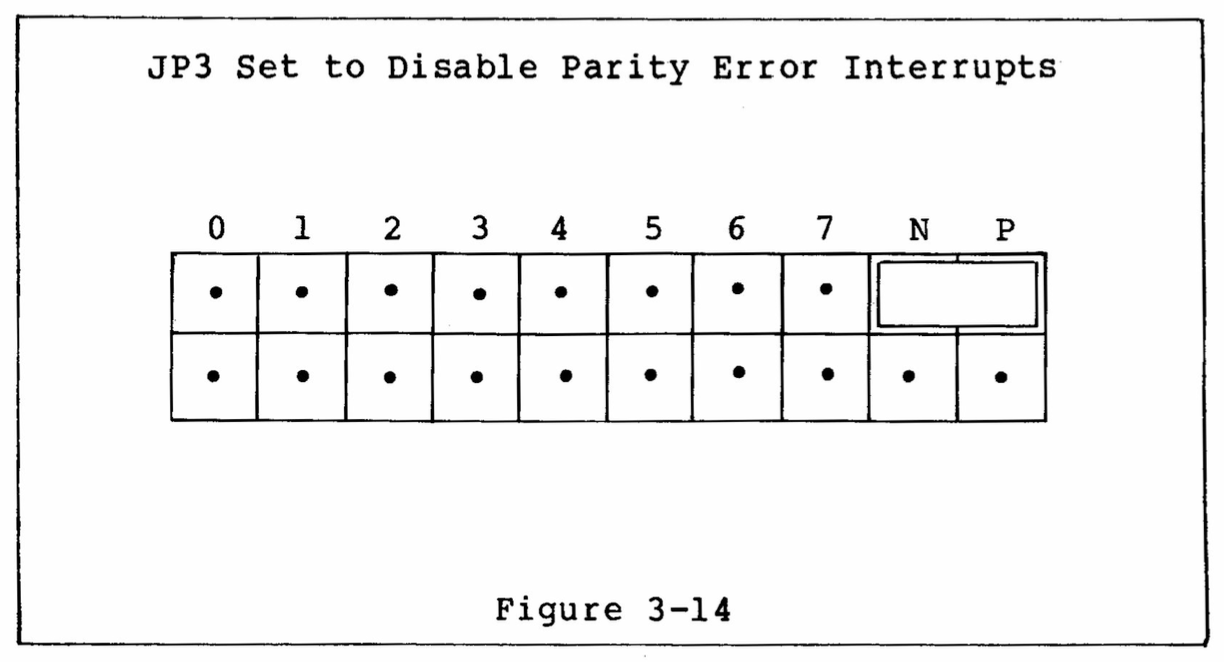
The first left column (9A-9D) contains the parity bit. The red LED (upper left) is for parity errors.

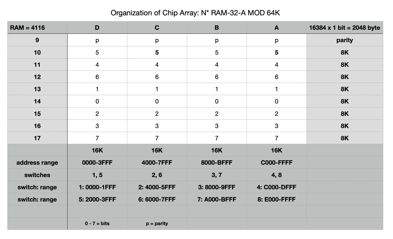
The IC's are uPD416C-1, 16,384 x 1 bit
-----------------------------------------
DIP switch settings: 7 x 8K = 56K
-----------------------------------------
1   ON      8K      0000 - 1FFF
2   ON      8K        4000 - 5FFF
3   ON      8K          8000 - 9FFF
4   ON      8K            C000 - DFFF
5   ON      8K       2000 - 3FFF
6   ON      8K         6000 - 7FFF
7   ON      8K           A000 - BFFF
8   OFF     0K             E000 - FFFF
-----------------------------------------
Order: 1 - 5 - 2 - 6 - 3 - 7 - 4 - 8

This order is also found in the original
BOARD AND CHIP SELECT. Here there are the
pairings 0-8, 2-A, 4-C and 6-E. Here only
one assignment could be selected from each
pairing, see below.
-----------------------------------------
-----------------------------------------
Memory test with my PROM monitor
-----------------------------------------
1   00 - 04K    0000 - 0FFF     OK
    04 - 08K    1000 - 1FFF     OK

2   16 - 20K    4000 - 4FFF     OK
    20 - 24K    5000 - 5FFF     OK

3   32 - 36K    8000 - 8FFF     OK
    36 - 40K    9000 - 9FFF     OK

4   48 - 52K    C000 - CFFF     OK
    52 - 56K    D000 - DFFF     OK

5   08 - 12K    2000 - 2FFF     OK
    12 - 16K    3000 - 3FFF     OK

6   24 - 28K    6000 - 6FFF     OK
    28 - 32K    7000 - 7FFF     OK

7   40 - 44K    A000 - AFFF     OK
    44 - 48K    B000 - BFFF     OK, S

8   56 - 60K    E000 - EFFF     PROM, FDC
    60 - 64K    F000 - FFFF     na, FF
-----------------------------------------
Order: 1 - 5 - 2 - 6 - 3 - 7 - 4 - 8

na  not available
FF  return from PROM memory test
E   contains PROM and FDC ROM
S   stack for the PROM, BF00-BFFF
-----------------------------------------
(but with 48K CP/M)
A Faulty DIP Switch
I also had the DIP switch problem described by Mike Douglas with this RAM card. A memory area selected by DIP switch but was not present at first.
Also, DIP switches are notorious for failing as they age. The failure mode is high impedance when the switch is closed. This typically makes what should look like a zero look like a one instead. In your case, one or more of the banks on the 16K board could then be overlapping the FDC. You can easily check for this by measuring across each switch with a meter. Flipping the problem switch(es) numerous times and optionally flushing with contact cleaner can make the switch work well enough to temporarily solve the problem. [13]
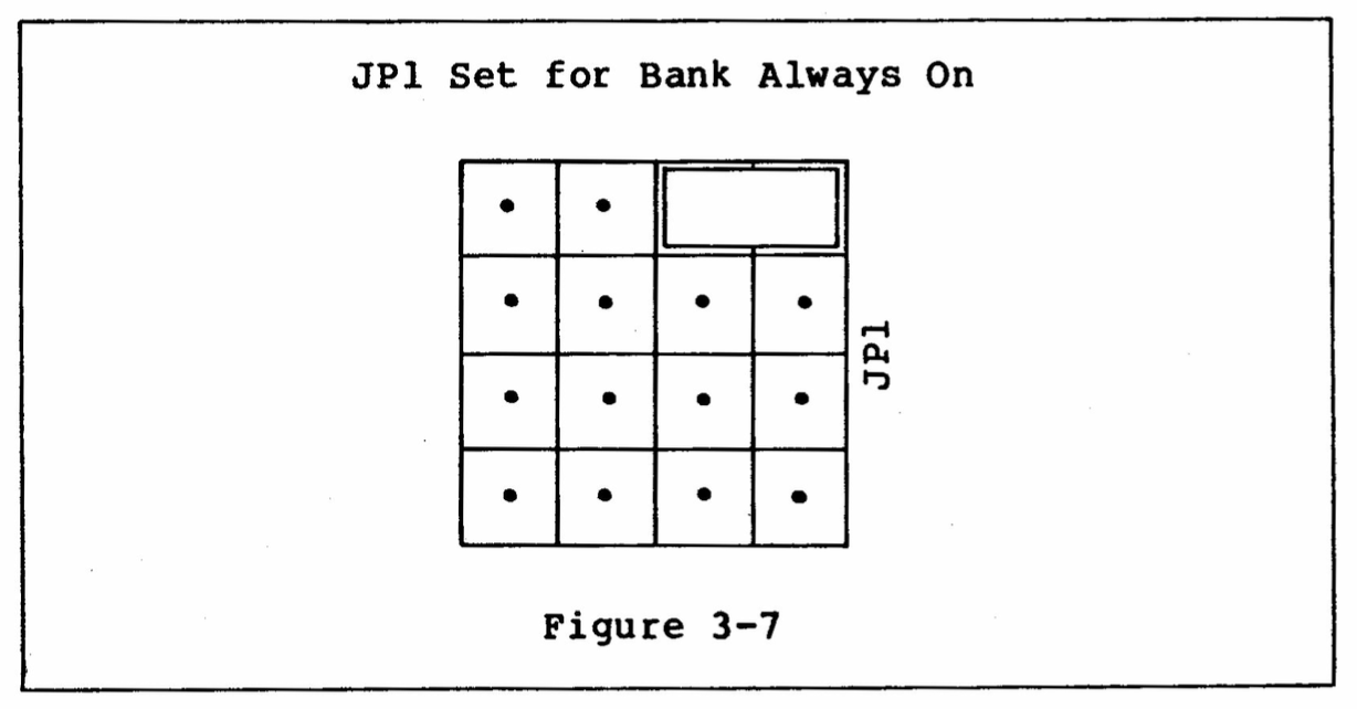
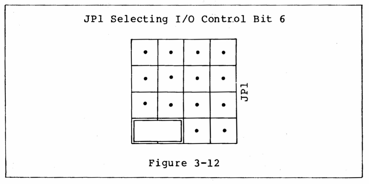
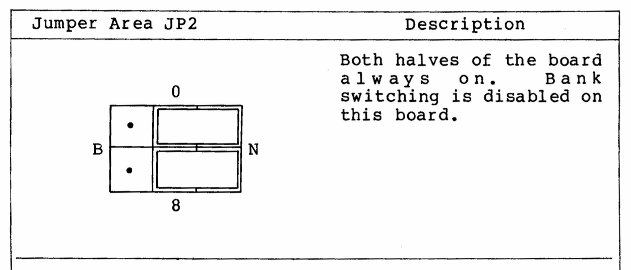
North Star HRAM-64 - Dynamic RAM - 64 KByte
This board is equipped with 4 x (8+1) AM9016EPC (16,384 x 1 bit, 200ns). A very big disadvantage of this board: all ICs (RAM, TTL) are soldered, not good at all!
Rasmussen memory test, 04/10/2023: 10 cycles, everything is OK.

The jumper and switch settings are very easy, see below. S1: block E000-FFFF is disabled. S2: all OFF.

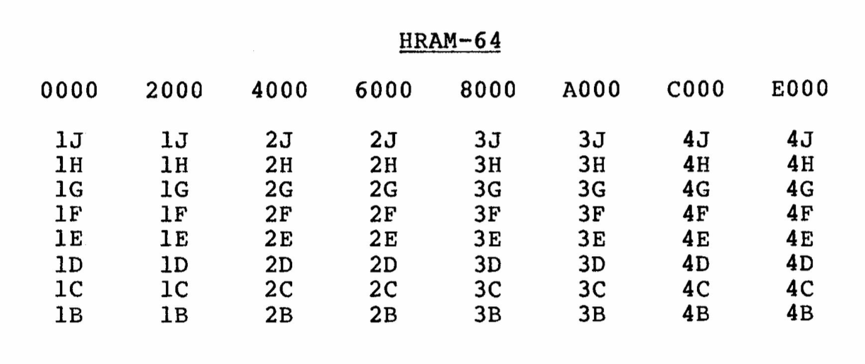
(1A-4A = parity)
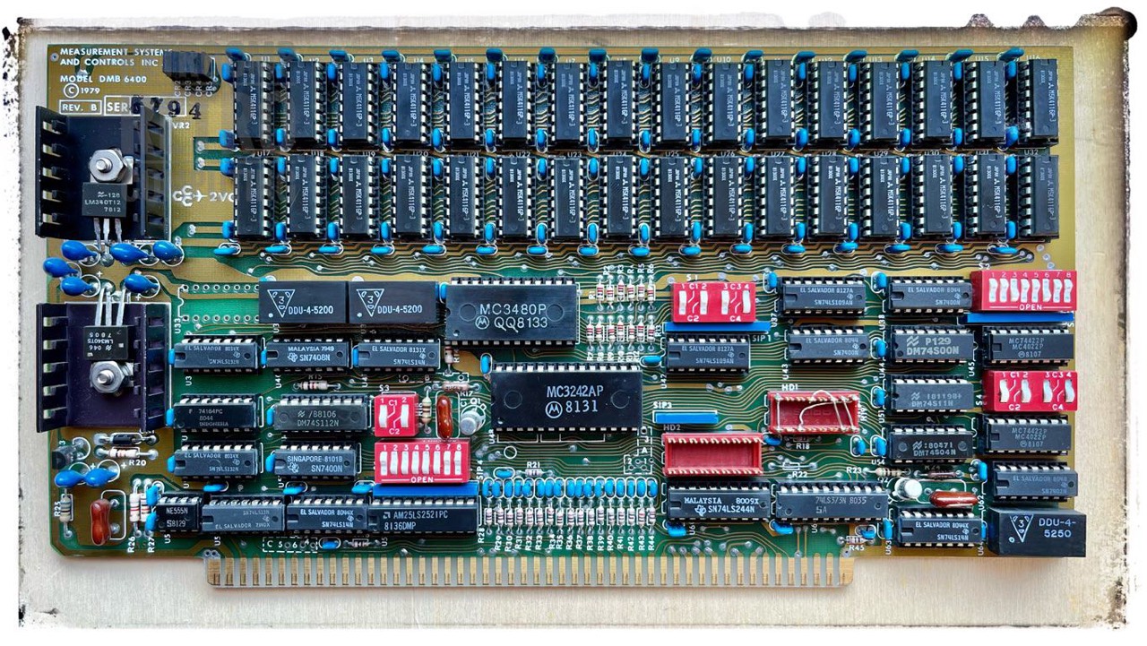
MSC DMB6400 - Dynamic RAM - 64 KByte
Note: The following rocker settings are not all identical to the picture above! Curently I use the settings listed next and so far my N* is working fine. I use a 48K CP/M of Lifeboat.
This RAM board almost drove me to desperation because it was running smoothly for three weeks, then it failed without warning, and now it's running perfectly again. Why?
Contacts, contacts and again contacts. On the one hand it was the DIP switch S2 and on the other hand the RAM contacts. So all RAMs at least once out and back in and treat the switch S2 with contact spray, better yet replaced completely. And then everything worked again.
This board is equipped with 2 x 16 M5K4116P-3 (16,384 x 1 bit, 200ns).
# S1 - Bank Select
If the bank select feature is not used, all four bank selectable sections should be turned ON at RESET for 64K byte memory. If it is desired to deselect 16K of memory, then turn that section OFF at RESET. [6]
- ON
- ON
- ON
- OFF
3 x 16K = 48K (I now use the PROM OPTION and the FDC PROM, therefore the last 16K bank must be switched off.)
# S2 - Bank Starting Addresses
- 0000h (- 03FFh)
- 4000h (- 7FFFh)
- 8000h (- BFFFh)
- C000h (- FFFFh)
I do not use S3, S4, S5 and header HD2!
# S3 - Phantom Clock
- ON - J1-67
- ON - 02
# S4 - Phantom Select
- OFF
- OFF
- OFF
- OFF
# S5 - Bank Select Address
From left to right -> 1 0 0 0 - 0 0 1 1 -> 1 1 0 0 - 0 0 0 1 -> C1h
According to the manual this shloud be an unused address if bank select is NOT used. I did not change the setting, just applied it. I have NO idea why C1h is set here.
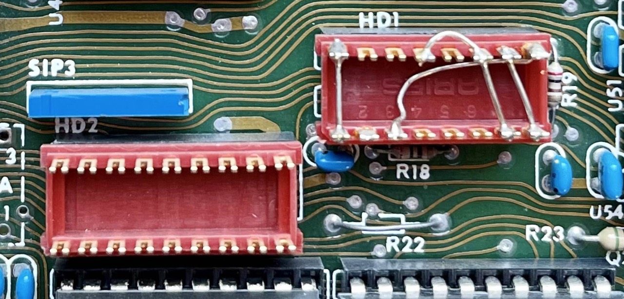
# Header HD1 & HD2
Header 1 is configured for the North Star Z80 (1-16, 3-9, 7-11-13, 8-10).
Header 2 is not wired because the bank select is not used.
CompuPro RAM17 - Static RAM - 64 KByte
From what I've heard in the S-100 community, the RAM17 is one of the best 64K static RAM boards. Easy to configure and very power efficient. Since Oct 2023 I use in my N* Horizon basically only 48K, because from time to time I use the Cromemco 8K Bytesaver.
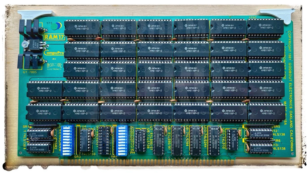
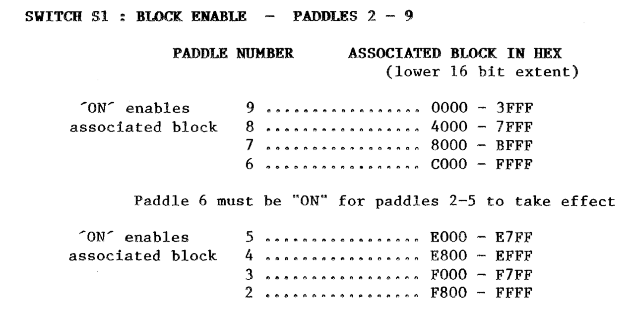
I use the RAM17 in NORMAL MODE.
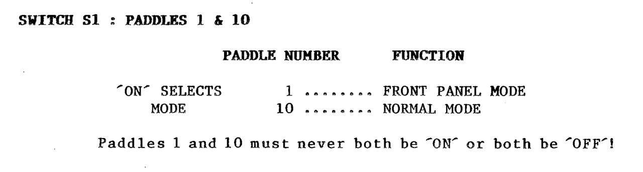
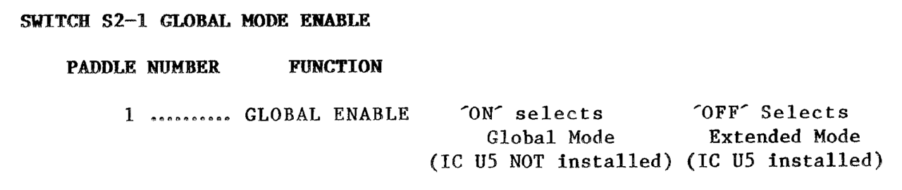
I use the RAM17 in GLOBAL MODE, IC U5 is not installed.
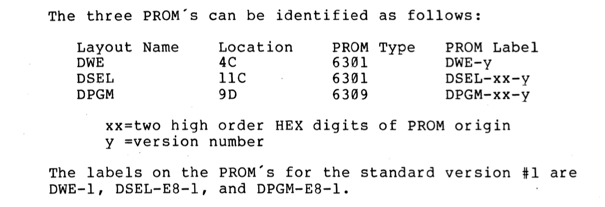
N* MDS-AD - Micro Disk Controller - DSDD
The original North Star MICRO-DISK System (MDS) controller is an integrated system of hardware and software.
The revisions that I know from pictures are:
- MDS-AD
- MDS-AD2
- MDC-AD3
This MDS-AD is a later floppy disk controller for the Horizon: single-sided, double-sided, FM and MFM. The very first (FM only) was the MDC-A.
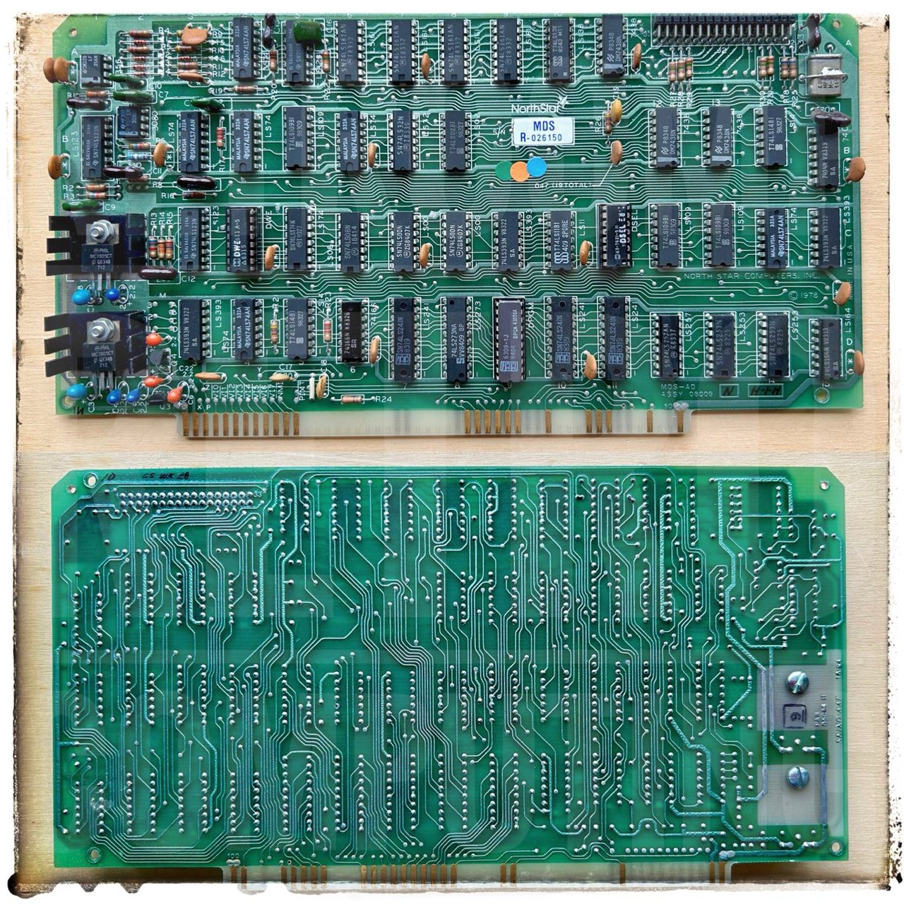
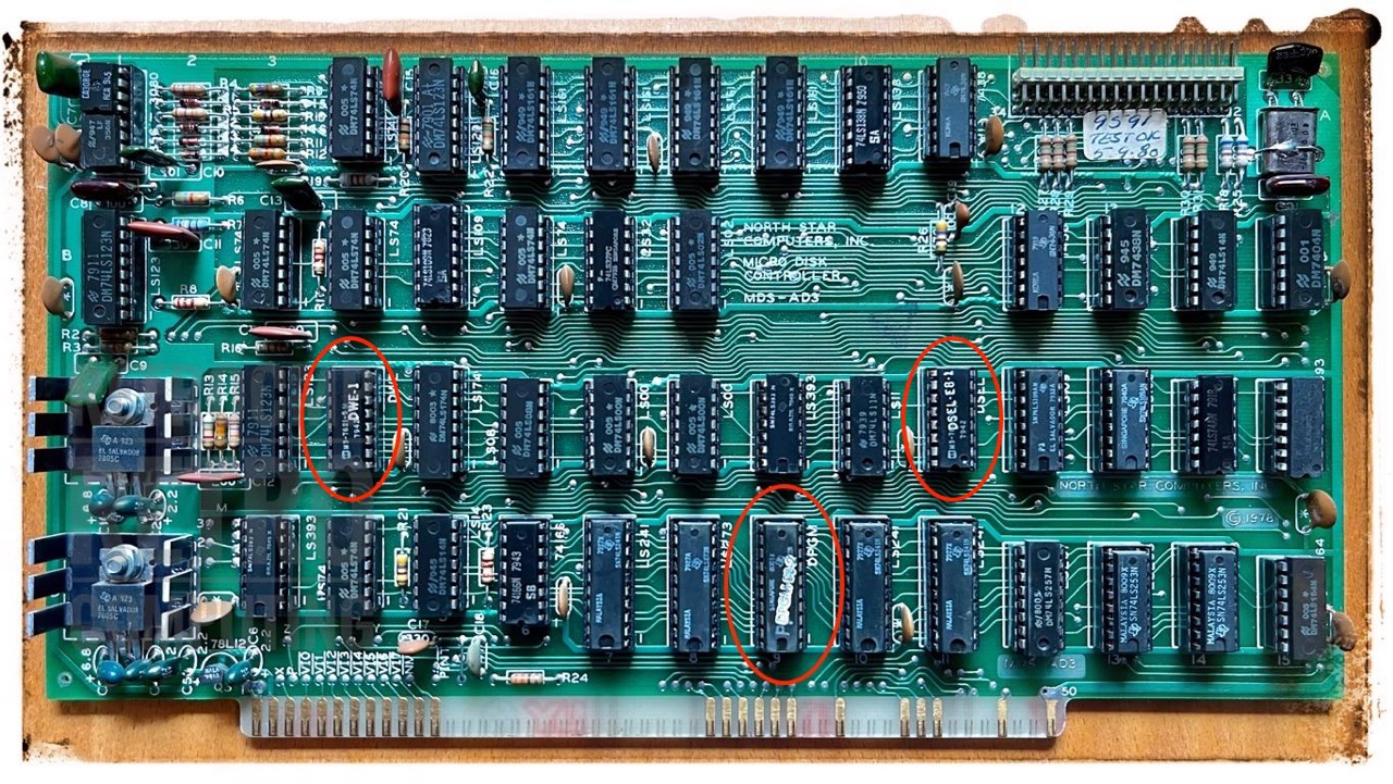
N* MDS-AD3 - Micro Disk Controller - DSDD
The PROM (DPGM, D9) on the micro/floppy disk controller is located at address E800 by default.
On board PROM: Bootstrap software (8080/Z80 machine code) is stored in an on-board 256 byte bipolar PROM (DPGM, 9D). This PROM provides 256 bytes of memory. The 8 low order address bits address the PROMs. The PROM outputs are driven onto the Data Input Bus. [7]
The contents of the PROMs are available for download from Mike Douglas.
To the floppy disk controllers of the North Star Horizon is to be said in principle that these react in the interaction with the floppy disk drive and the hard sectored floppy disks very sensitively to deviating or fluctuating speeds. Therefore, the newer half-height ones are better than the old ones with belt drive.
The hard sectored N* is more fussy about the sectors than the Heathkit H17 was. ... The controller on the N* keeps track of the sectors by a counter. It isn't quite as fussy about 300 rpm as you might think. It does expect the drive to be up to speed in only a few sectors after enabling the drive. It has a limit on the amount of time between sectors before the controller will error out. I forget what it was but it is controlled by a crystal divider, as a counter. [8]
N* MDC-A4 - Micro Disk Controller - SSSD
This MDC-A is the very first floppy disk controller for the N* Horizon: single-sided (SS), single-density (SD, FM). You can not use double-density (MFM) disks.
The revisions that I know from pictures are:
- MDC-A1
- MDC-A2
- MDC-A3 (not yet seen ¯\_(ツ)_/¯)
- MDC-A4
[Herb Johnson] Confusion about Northstar MDS and MDC floppy controllers
The Northstar floppy controller board named "MDC" was a single-density controller, first sold by Northstar around 1976. It was sold as part of their "MDS" system of controller, cables, drive cabinet with power and drives, and their operating system. This was one of Northstar's first products - a floppy disk system upgrade for S-100 computers like the MITS Altair, the IMSAI, the Processor Tech SOL, and so on. That's where the MDS/MDC confusion began.
The Northstar floppy controller board named "MDS" was a single or double-density controller, first sold by Northstar around 1978. By then, they produced the Northstar Horizon S-100 system with this product; and they may well have continued to sell their packaged disk system.
The two boards both have program PROMs; either one or two depending. They also use a PROM for address decoding. these are all small bipolar or fuse-link PROMS, easily overlooked as "logic ICs". Refer to parts lists and schematics for specifics on those PROMs. the locations of the PROMS confirm which schematics and docs "go with" which board. [16]
The contents of the PROMs are available for download from Mike Douglas.

I have removed all TTL ICs from this board and tested them with a simple IC tester (POLAR D320). Result: 1x 7438 is defective. And I checked the pins for corrosion and black tarnish. I have had very bad experiences with the TTLs from Texas Instruments. Almost without exception, the pins are tarnished black. This is silver sulfide. Silver sulfide is an electrical non-conductor and should therefore be removed.
Then I replaced the one tantalum capacitor (25V, 6.8uF) and two ceramic capacitors (473, 25V, 0.047uF). They just didn't look good any more, tarnished or already slightly chipped. Get rid of them, there's no point in keeping them. But keep the old parts.
And then the chicken and egg dilemma arises again. How do I get a boot image copied to a new HS10 disk? Also, I have never been able to test this controller because I don't have a boot disk. But none of this is a problem, because Mike Douglas has done some excellent groundwork here. All you have to do is start your N* Horizon with the Vector 4.0C monitor. Now read in the PCFLOP program as Intel HEX and start it with the help of the monitor. Then you can read in the corresponding NSI image via XMODEM and copy it directly to drive A:. Then restart and ... see for yourself, it worked.
Booting a single-sided, single-density floppy disk:

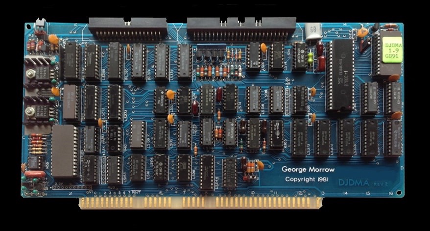
Morrow - Disk Jockey DMA - Floppy Disk Controller
I do not own this controller, but I am currently (09/2023) in email contact with an N* Horizon owner (J. Haug) who uses this controller.
The Disk Jockey/Direct Memory Access (DJDMA) floppy disk controller was a single board for the S-100 bus. It communicated with both 8 inch and 5 inch floppy disk drives. Up to eight drives could be connected to the controller - with the limitation that no more than four of each type could be accommodated.
Special programmable bipolar LSI logic made it possible to read and write media in almost any format, be it hard or soft sectored disks. Normally the controller was used for soft-sectored IBM compatible 8 inch media.
However many used it for hard-sectored North Star compatible 5 inch media. [18]
You can read and write double-sided diskettes if you have double-sided drives (and diskettes). Single-sided drives have only one read/write head, so they can't handle two sides of a diskette. The DJ/DMA is capable of distinguishing single from double sided 8" diskettes because they are physically different. The DJ/DMA can also recognise double-sided Micro Decision diskettes and NorthStar diskettes by looking at a byte in the first sector of the diskette. [19]
But you need a customized CP/M from Morrow with BIOS mods to work with the North Star I/O.
Power Supply Unit - PSU

Basic setup:
- power grid 230 VAC / 50 Hz ↓
- isolating transformer 230 VAC ↓
- 95 VAC (!) ↓
- → N* components
Components:
- Transformer
- Rectifiers
- Capacitors
What stands out immediately? Until now, I only knew the so-called switching power supplies. Here in the North Star Horizon, however, a transformer power supply is installed. Simple in design, incredibly heavy, consumes a lot of power (even in idle mode) but it lasts (almost) forever.
In the product catalog of Aug 1979 the PSU is given with 250 watts (domestic and international).
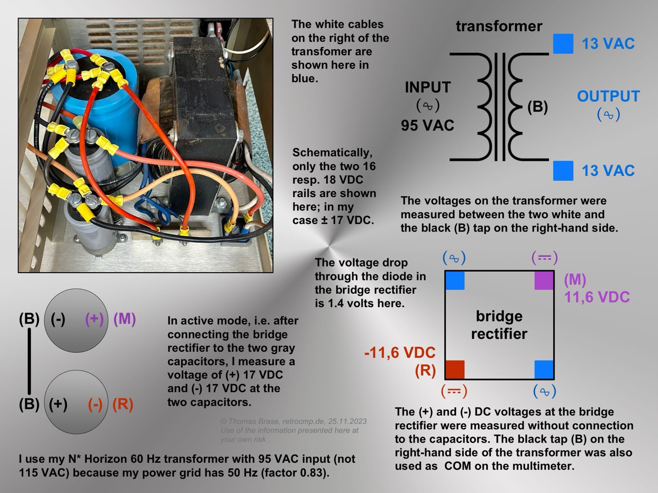
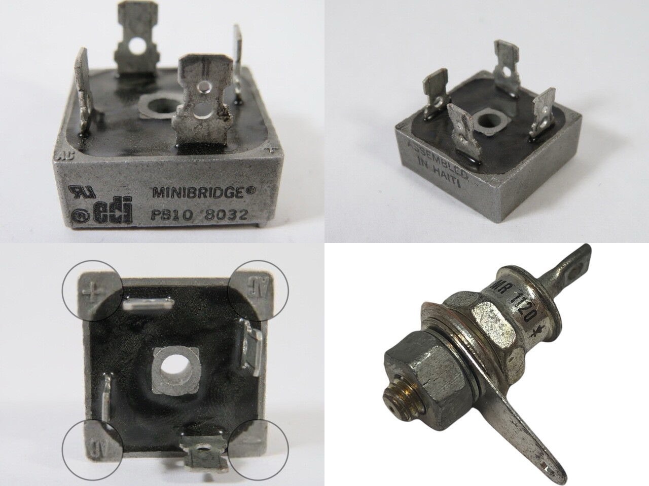
- Bridge rectifier (edi PB10, 100V, 25A): input +13 VAC, output ±17 VDC
- Rectifier (MR 1120, 1N1581, 1N1199B; 50V, 3A): input +7 VAC, output 9 VDC
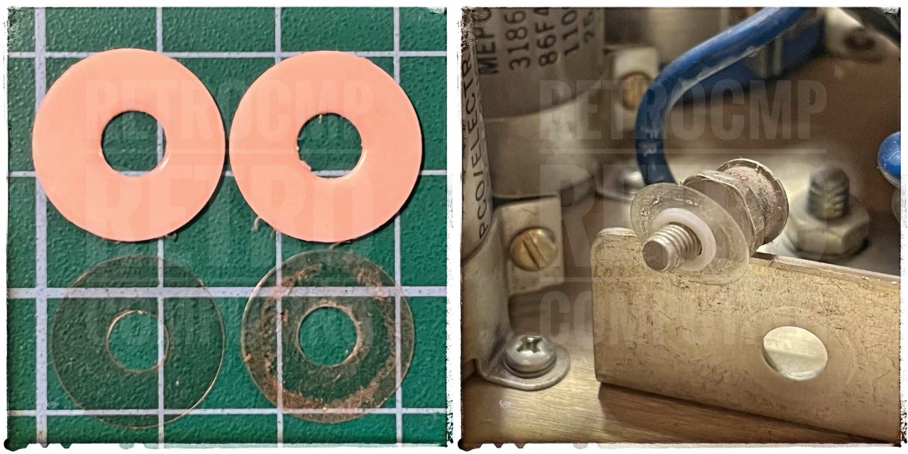
When exchanging the capacitors, pay attention to the polarity!
- +8V
- +16V:
- -16V: watch the polarity!
(---)(+++)
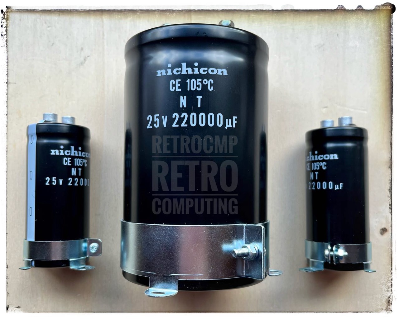
15V, 180,000 uF (MFD)
77 x 120 mm
MALLORY Type CGS, 20-98583, 235-8011K
(---)(+++)
25V, 11,000 uF (MFD)
35 x 80 mm
TAZCAP 7946
(+++)(---)
25V, 8,900 uF (MFD)
35 x 80 mm
TAZCAP 8008
You can get (even today in 2023) nearly matching new capacitors from Nichicon (LNT series, screw type). They are only expensive. The two small ones cost about 17 EUR/piece and the big capacitor about 70 EUR!
You no longer get the capacitors with exactly the same parameters, but almost. I took all three from the 25V LNT series and always the next higher value for the capacities.
The replacement is quite simple, only the reinstallation of the screws at the bottom is quite fiddly. Actually, I didn't need to change the three capacitors at all. But I was curious and now the power supply should be fine again for the next twenty years. I still have a whole set in stock for my second Horizon.
Reactivating the old Capacitors
Update 06/27/2023: In the meantime, 4 months have passed between today's and the following and I have become smarter. I would not reactivate this large capacitors in the same way now, because it could have gone wrong. But I was lucky. In the meantime I have created a separate chapter for it: Reforming large old capacitors.
North Star Horizon (S/N 14-326)
Today (02/04/2023) I put the power supply into operation for the first time; without mainboard and drives. I have connected a variable transformer. As loads I have connected two old 12V fans (on the picture is only one). The other one was added later. And so the original power supply runs at first with about 50 volts input voltage instead of 110V.
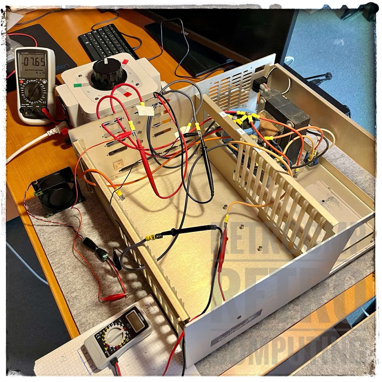
Temporarily I increased the variable transformer from 50V to 115V input voltage. The DC output voltages were then about +11V, +21V and -21V. This information agrees with information from the Internet.
And what about the "large" capacitors? See next, DC voltages after switching off (no fans connected).
- 10 min: +10.4V, +18.2V, -18.2V
- 15 min: +10.0V, +17.2V, -17.3V
- 35 min: + 9.7V, +16.5V, -16.6V
With other words. Even after 30 minutes the voltages in the three large capacitors are OK.
North Star Horizon (S/N 18-916)
Today (02/26/2023) I put the power supply of my 2nd N* Horizon into operation for the first time; without mainboard and drives. I have connected a variable transformer in front. As loads I have connected old old and one modern 12V fans.
And so the original power supply runs at first with about 66V volts input voltage instead of 110V. At this voltage, the large capacitor gives off about 5V; just enough to move the modern 12V fan. With the -volt capacitor, all you have to do is swap the lines and the fan will spin.
So every 10 minutes I turn the Variac to 66V and let the power supply do its work for about 5-10 minutes. After that I reduce to 0 volts and wait again. Because of the fact that a consumer is connected to all three capacitors, they are almost completely discharged. This is important, at least that's what I read on the Internet. I will carry out this procedure the next few days and so the load very slowly increase to 110 volts. I assume that the power supply and capacitors have not been energized for the last thirty years. So, don't be in a hurry.
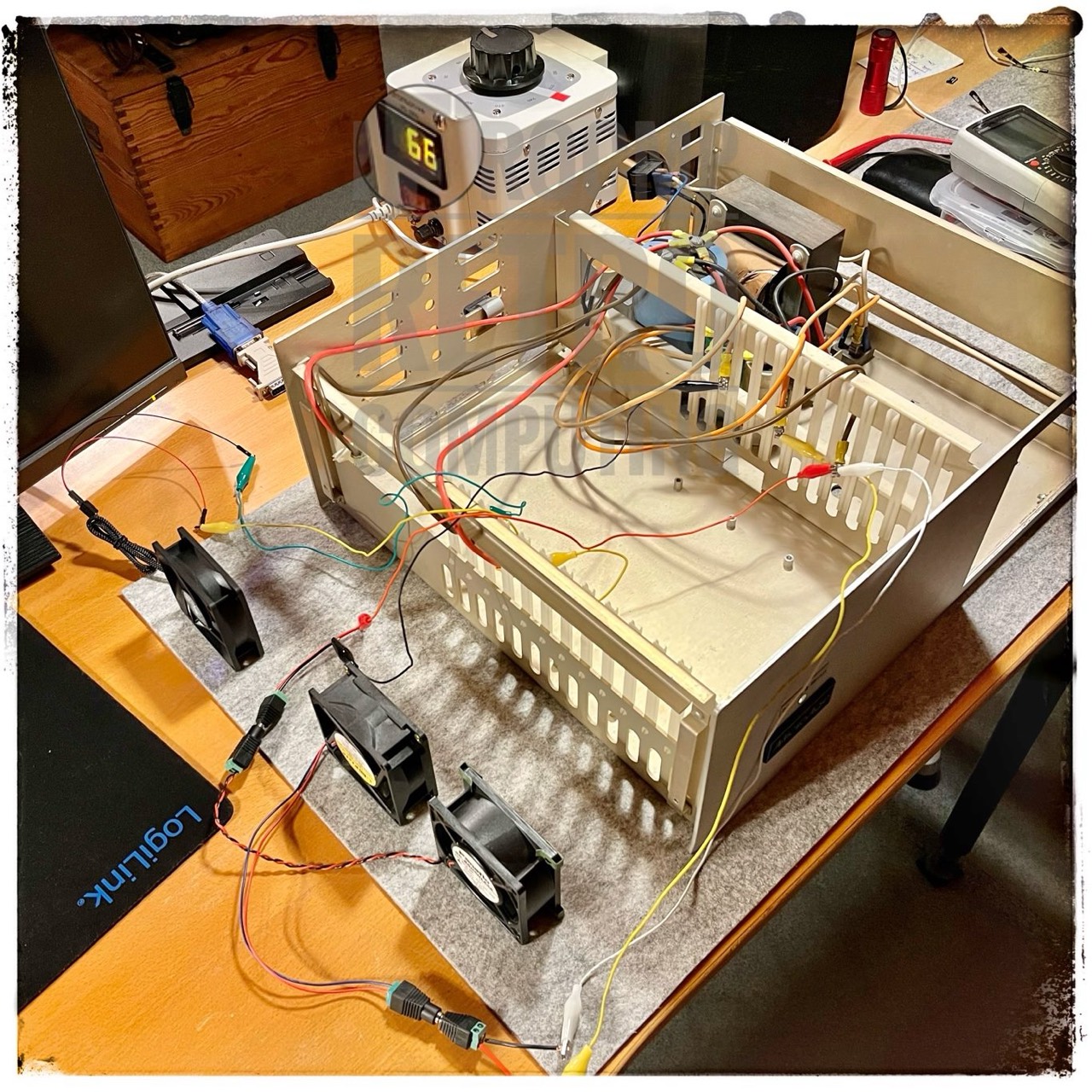
PSU/Caps & Mainbord (without ICs & S-100 cards)
As loads I connected an old and heavy 12V/0.3A fan to the large capacitor (nominal +8V) and two modern IDE hard disks to the two Molex connectors for 12V/5V.

Input AC 110V from variac to PSU. The DC output voltages are:
- From capacitors onto mainboard:
- (1) ........ (-16V) -19.9V
- (3) ........ (+16V) +19.7V
- (6+7) .... (+8V) +9.9V
- Molex plug 1 .... +12.31V, +5.04V
- Molex plug 2 .... +11.97V, +4.93V
As a test, I connected an IDE hard disk to both Molex connectors. The maximum consumption is +5V/800mA and +12V/2500mA. An old Shugart 400L or Tandon TM100-2 are at +5V/600mA and +12V/900mA. So at +5V both are quite comparable. The 7805 regulators get really hot. The operating temperature range is specified as a maximum of 125 degrees.
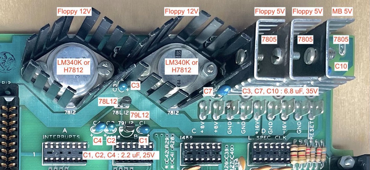
No smell. no smoke. I am satisfied with the result. The higher voltages (from capacitors to mainboard, no 1+3) also seem to be OK, according to what I have read so far.
Reducing the Heat Generation
The three heat sinks (top right) on the 7805 regulators become very hot under load. My solution, see next.
On the left side of the fan, I applied (later) a strong adhesive double-sided tape; it sticks perfectly.
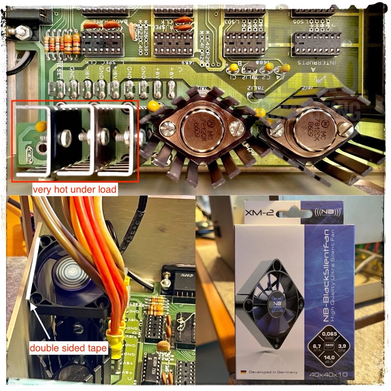
Under full load - PROM memory test and two IDE hard disks (only for test purposes) - all three 5V regulators do not get warmer than 30° C (86° F).
Reducing the Input Voltage!
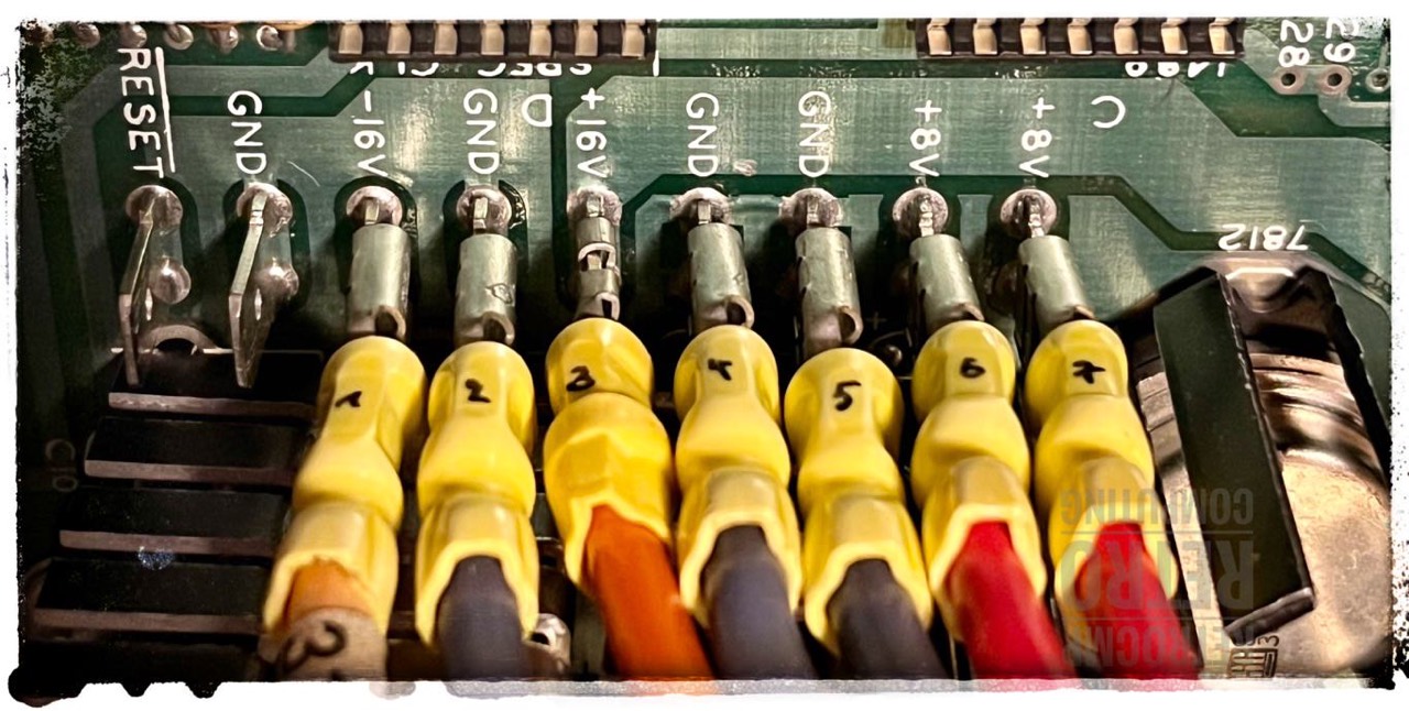
According to IEEE 696 the S-100 bus is operated with +8V/+16V/-16V by default. [9] But in fact my N* is operated with +10V/+20V/-20V at 110V input voltage.
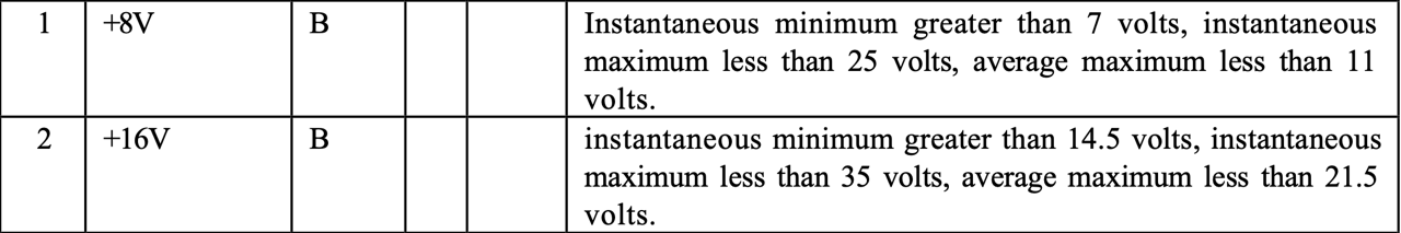

I have now adjusted my variable transformer (variac) so that the voltages on the mainboard are exactly at +8V/+16V/-16V DC. This requires only 92V AC input and not 110V!
Especially the 5V regulators (7805) sometimes generate a lot of heat. Therefore it is better if less voltage arrives. Why regulate down from 10-11 volts to 5V, when 7-8V are already sufficient.
This approach is also recommended by Herb Johnson (Dr. S-100). He also runs some of his S-100 computers with a variac. Herb discusses this topic in detail in: S-100 Power Supplies.
Attention: These specifications are valid for "my" power supply. It might be different for another one. Herb Johnson writes for example that his North Star Horizon power supply provides only +7V on the +8V line even at 110V AC.
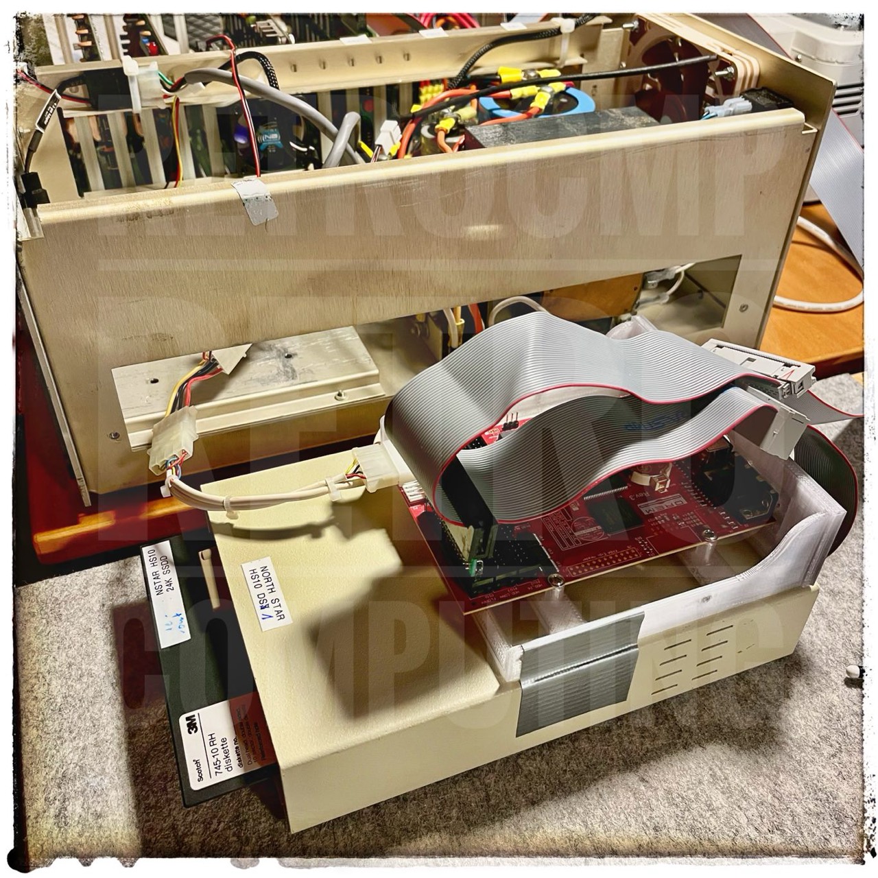
Floppy Disk Drives
My North Star Horizon had 2 full height floppy drives installed. One was a Shugart SA400 (single-sided, probably still an original drive) and then a Tandon TM100-2 (double-sided). The SA400 works properly, the TM100-2 not.
Today (02/22/2023) I connected the SA400 to the Horizon as drive C (DS3). It runs whisper quiet, the RPM is 301 RPM and reads flawlessly the floppy disks I created with the TEAC FD-55B/BV.
I am currently (Feb. 2023) using two wonderfully matched TEAC FD-55 drives. With a bit of skill, I was able to fit both drives in the far right of the case, with two black covers to the left. The mounting plate used would even allow me to fit a third drive.
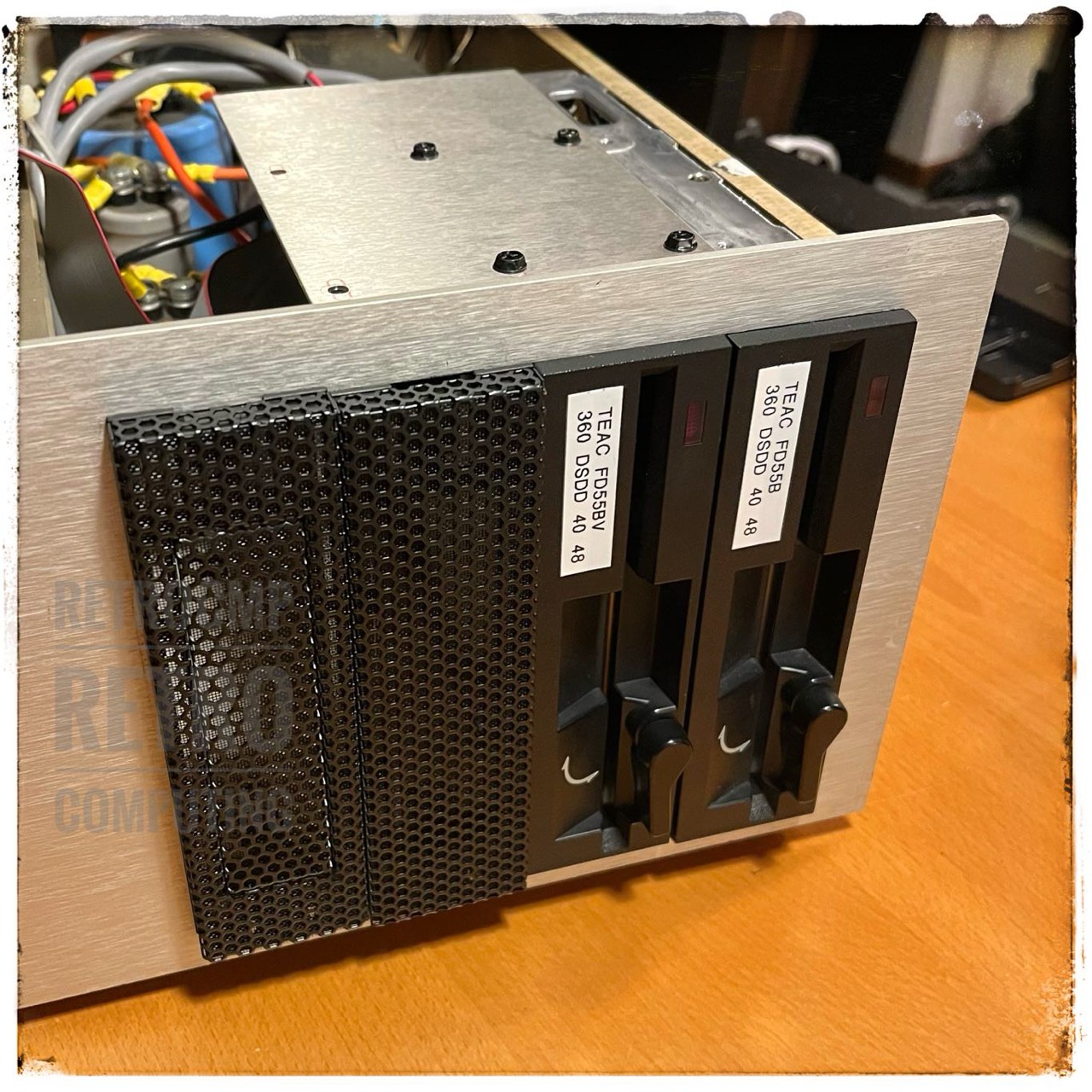
Four drives don't fit in the case, because then the small capacitor from the power supply is definitely in the way on the far left. The only disadvantage is that the floppy package can only be attached with two screws; hence the upper mounting plate. As long as the Horizon is horizontal, however, that's not a problem.
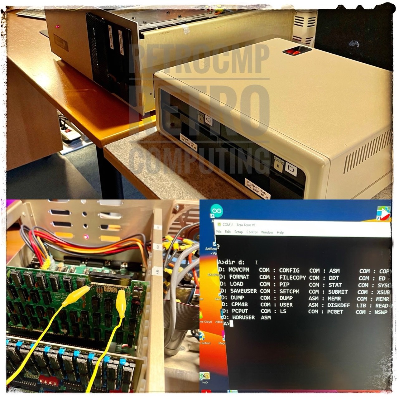
I am currently (Oct. 2023) using the COPAL Fujitsu M2551A (A:) with the DREM (B:). The DREM has a SD card and you can simply add or change files in the image.
The North Star Horizon can be operated with the following floppy drives:
- COPAL (FUJITSU) M25511A - A very good and silent drive for the N*, I like it.
- QUMETRAK 142
- Siemens FDD211-5 (aka World Storage)
- Shugart 400, 400L, 455
- TANDON TM100-1, -2
- TEAC FD-55B, FD-55BV
The special feature actually is that the drive has to cope with the pulses of the 10 sector holes (plus one index hole).
Using 4 Disk Drives
Yes, you can use four floppy disk drives an a North Star Horizon, but ... read on carefully.
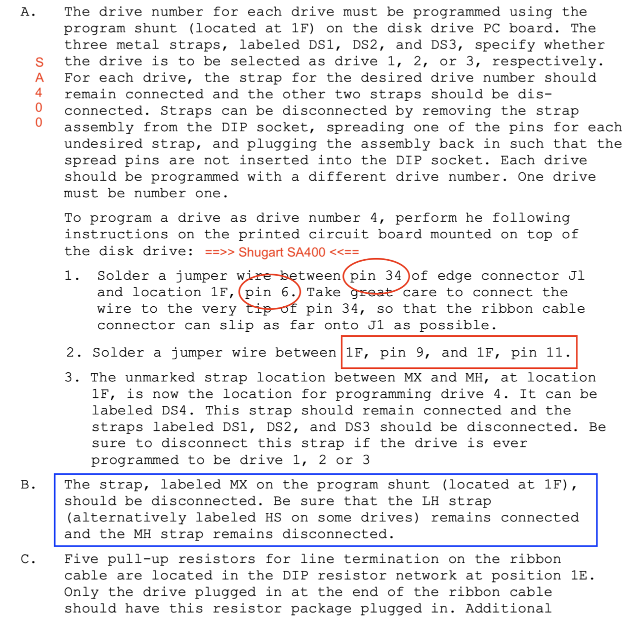
Drives 1 to 3 are set as usual with DS1-DS2-DS3 on the Shugart SA400. But for drive 4 you have to make a modification, because the North Star controller transmits the signal DS4 via line 34 at the floppy cable and not via line 6! Note, the SA400 has no DS4, you have to make/mod it yourself.
!!! WARNING !!!
Here my E-mail correspondence with Mike Douglas on this topic (a Shugart 400L):
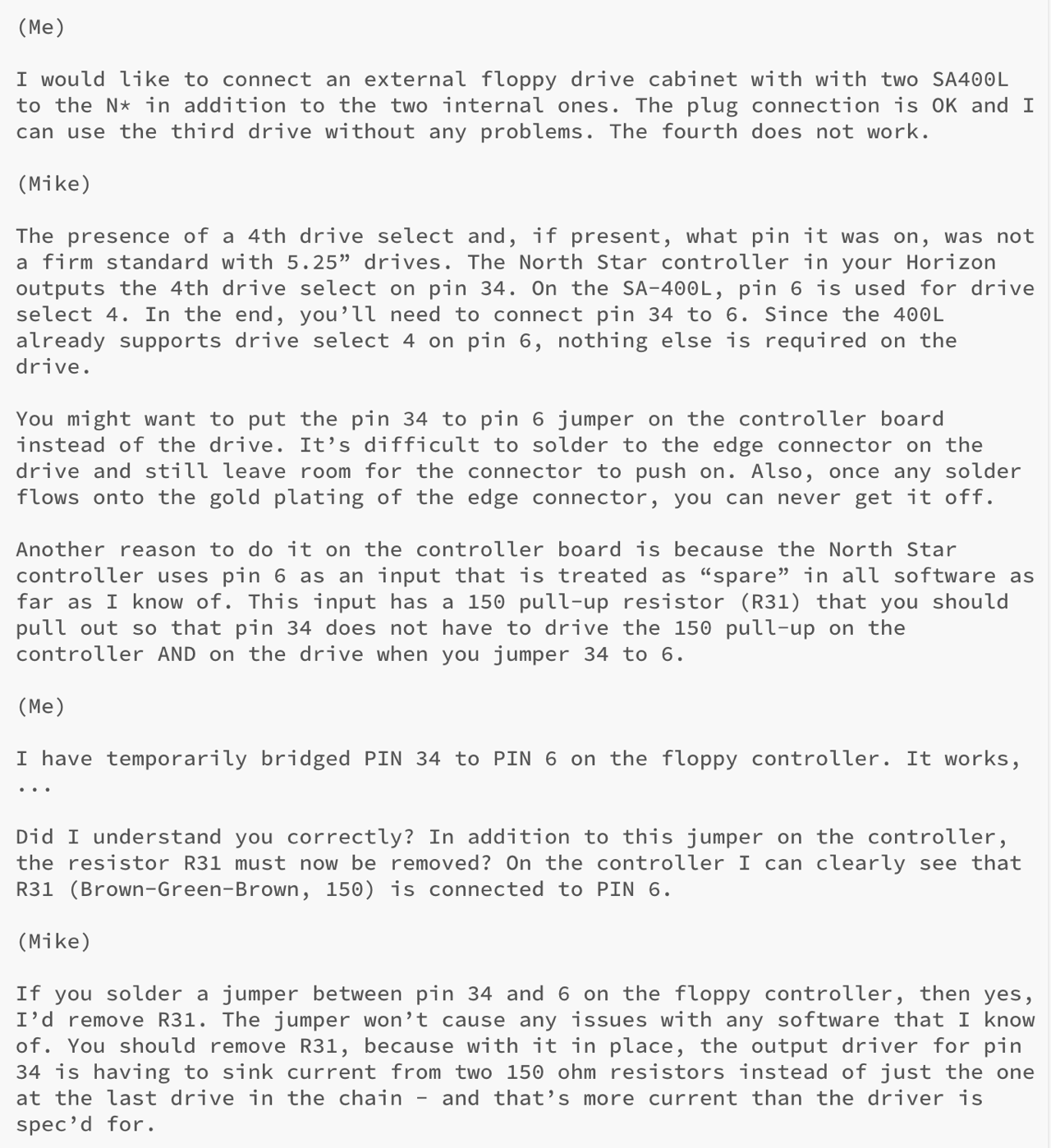
According to Mike Douglas you have to remove R31 on the floppy controller if you make a jumper from PIN 34 to PIN 6.
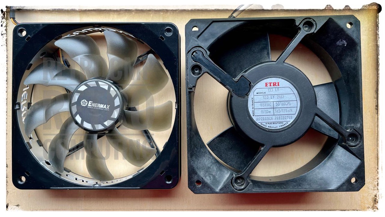
Cooling Fan
The 110V fan operates surprisingly quietly, but it rattles minimally at full load (110V). At about 80V, it runs perfectly. I think I may replace this with a modern 12V fan. However, I am not quite sure yet. Let's see.
Parallel Port
My parallel port with external adapter from DB15 to DB25. Works fine with my parallel printer Star LC24-20.
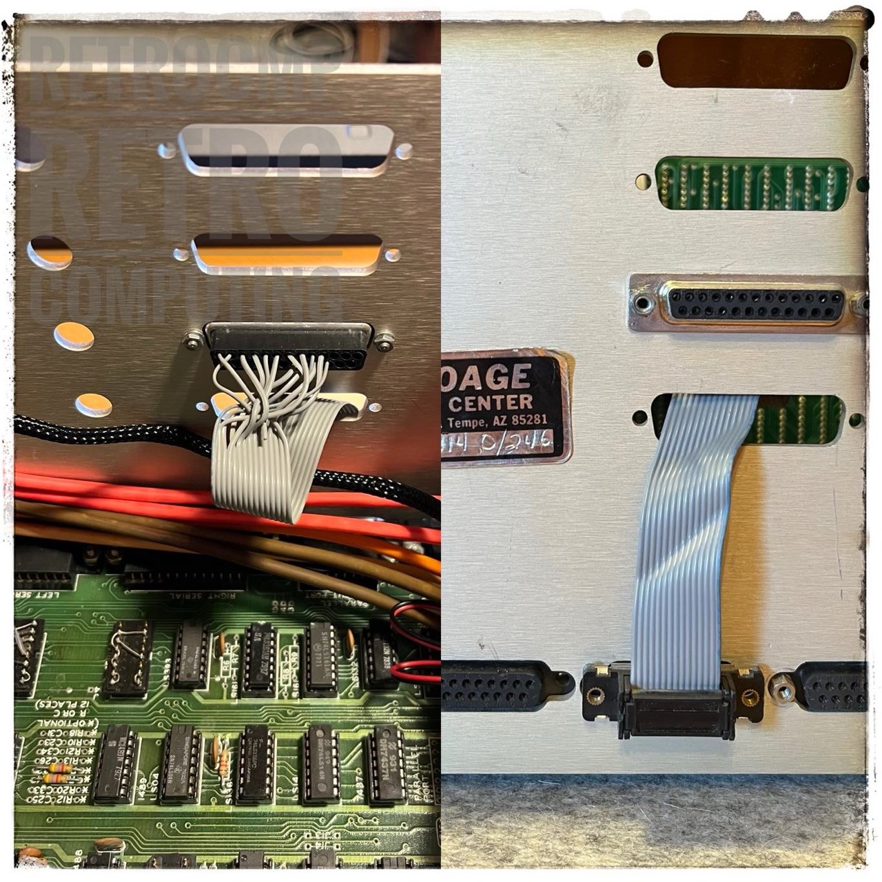
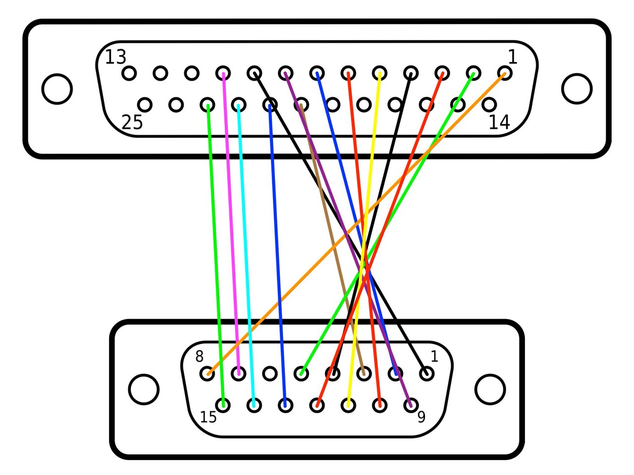
DB15 01 02 03 04 05 06 07 08 09 10 11 12 13 14 15
DB25 09 07 20 04 02 nc 10 01 08 06 05 03 21 22 23
Now check if the printer port is set correctly to parallel and print ...
SETCPM v2.2 for Lifeboat CP/M2 on North Star (c) 1981 M. Dubno

Auto message     : "AUTO"
Activate on      : No boot set          THREE drives
Interrupt enable : OFF                  Read after write : OFF
Printer on : Parallel port

A>pip lst:=memr.doc
Try CRTL-P and type DIR when your printer in online. See what happend.
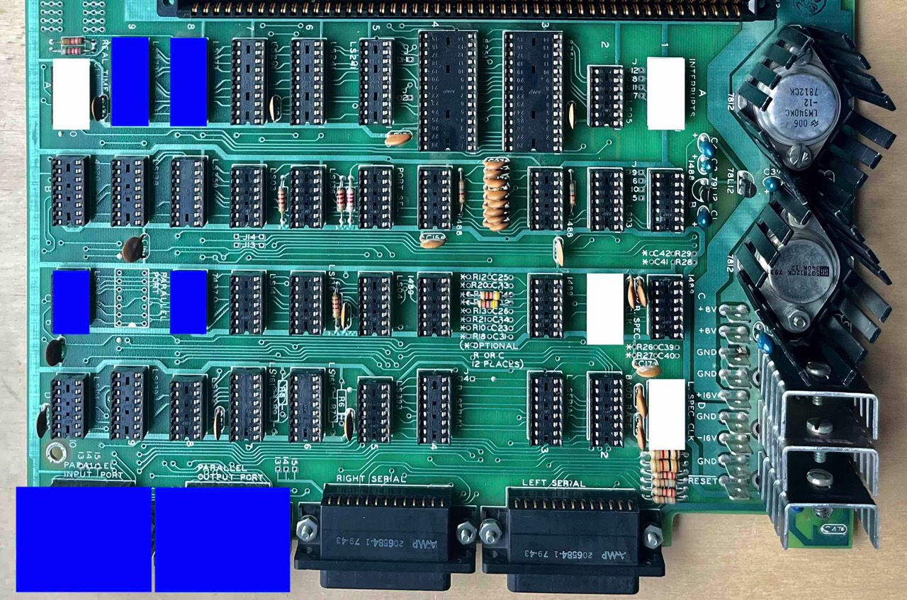
No Parallel Option
Using a picture of a Horizon motherboard without the two parallel ports, I marked the ICs that are (probably) used for this. As a test, I removed the corresponding ICs (blue) from my working Horizon and, lo and behold, it continues to work perfectly.
The white sockets (dip header) are also not required for the standard configuration; they are only needed for interrupt handling and the real time clock (RTC).
Terminal
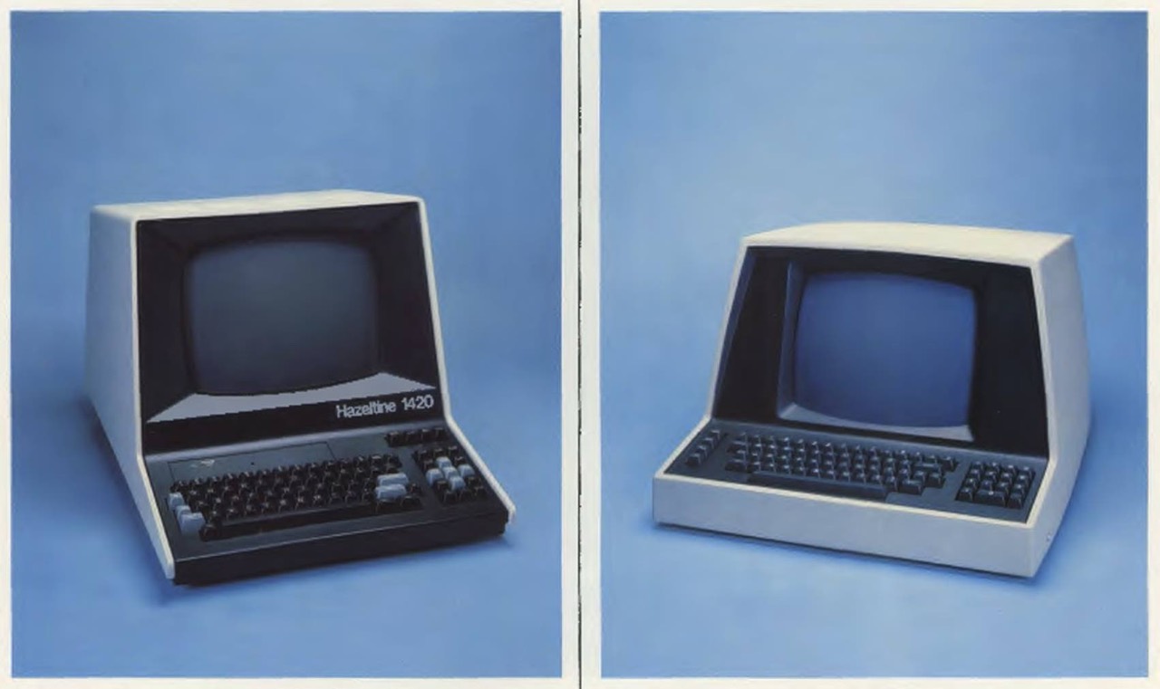
Either you are the owner of a real "old" terminal (with keyboard included) like the SOROC IQ 120 or HAZELTINE 1420, or you simply use your DOS, Mac or Windows computer. You can find appropriate terminal programs on the Internet.
The most important thing is to have the right settings on the Horizon mainboard and the right cable. Please take a look at the manual, below are a few excerpts.
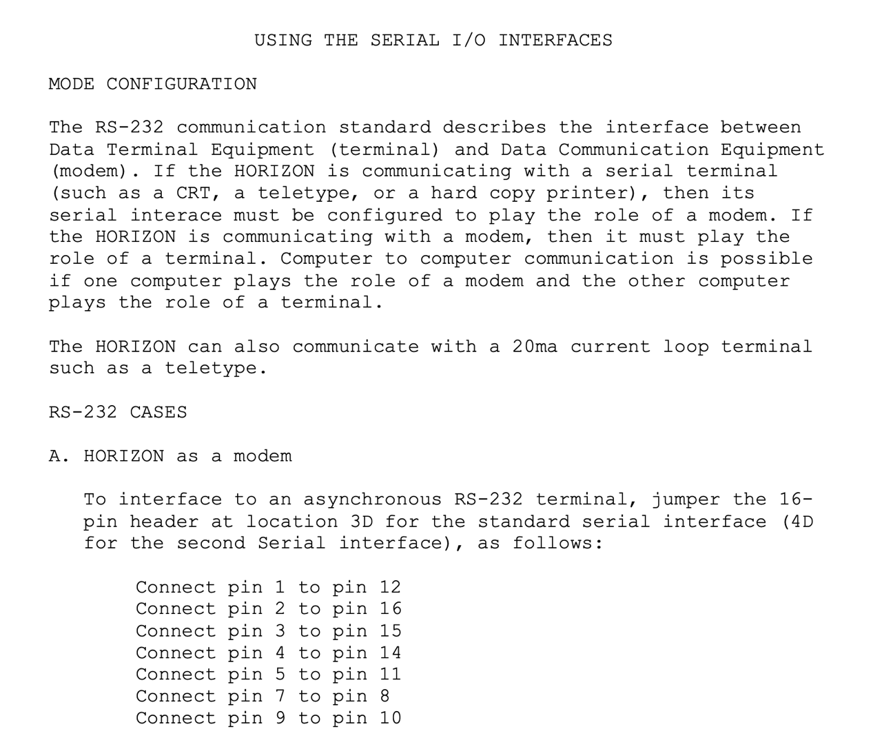
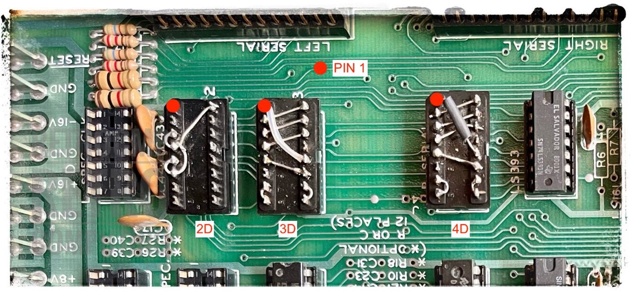
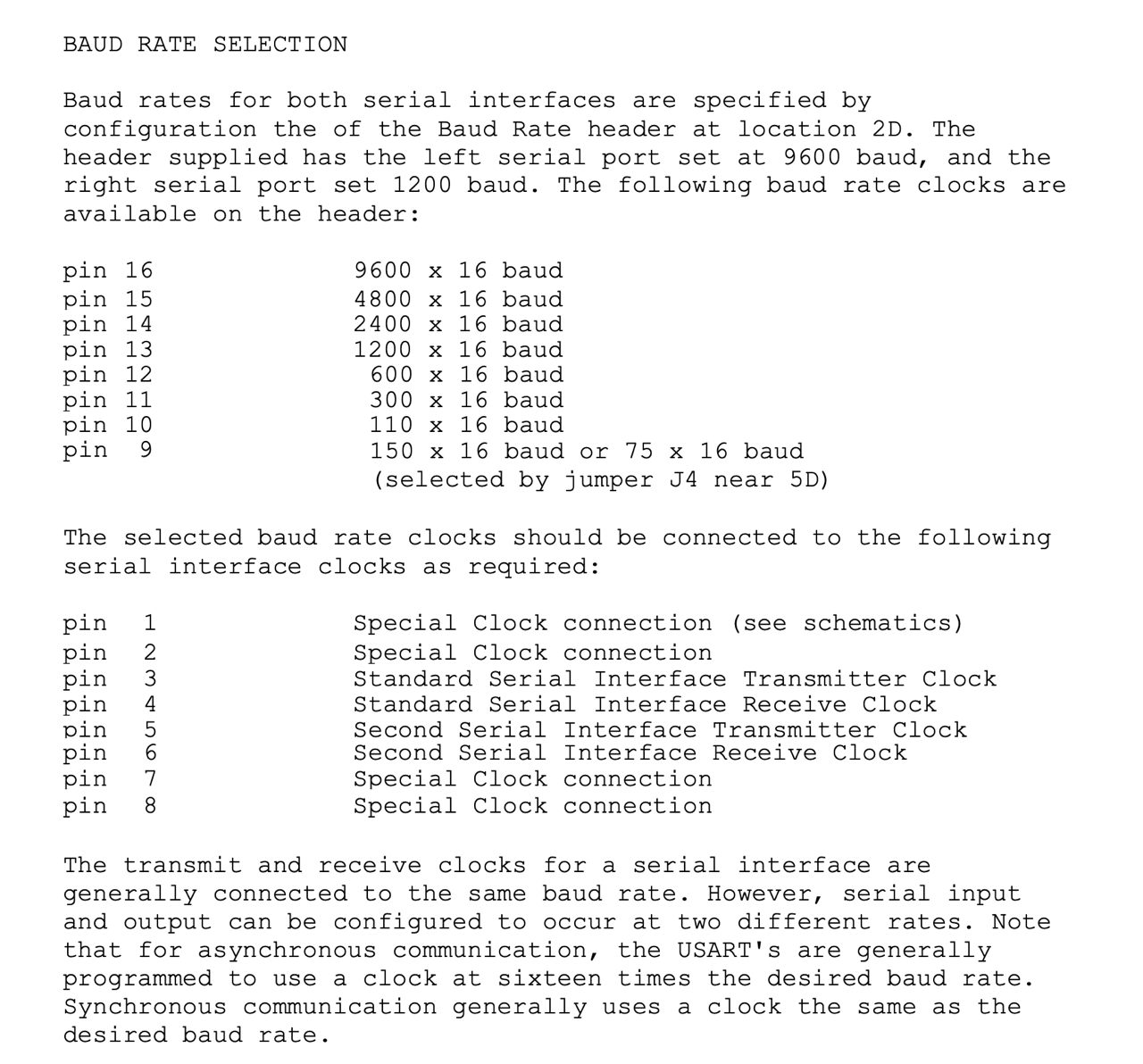
With me, both baud rates are set to 9600! The serial cable is straight through, with other words, it is not a null-modem cable!
CP/M
CP/M, originally standing for Control Program/Monitor and later Control Program for Microcomputers, ... [3]
I use currently the following version:
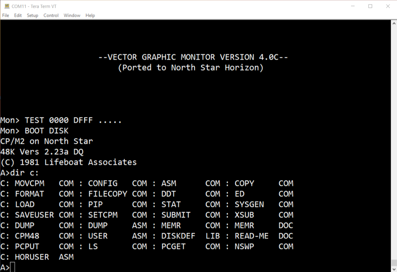
CP/M2 on North Star
24K Vers 2.23a DQ
(C) 1981 Lifeboat Associates
The software comes from the software pool of Mike Douglas (deramp.com). This version has the advantage that it only uses 24K RAM at the beginning and that was very important to me. Later you can easily adjust this to your RAM size with the command MOVCPM.
This Lifeboat version is well documented by Mike Douglas and Dave Dunfield. There is also an "unmodified" distribution disk/image (by Dave Dunfield), named C223A_24.NSI
In the beginning North Star was a non-CP/M system with its own DOS (North Star DOS). The adaptation to CP/M came later. This was done by Larry Alkoff of Lifeboat Associates. [5]
Today (02/11/2023) I reallocated the CP/M from 24K to 48K (with MOVCPM 48 & SYSGEN).
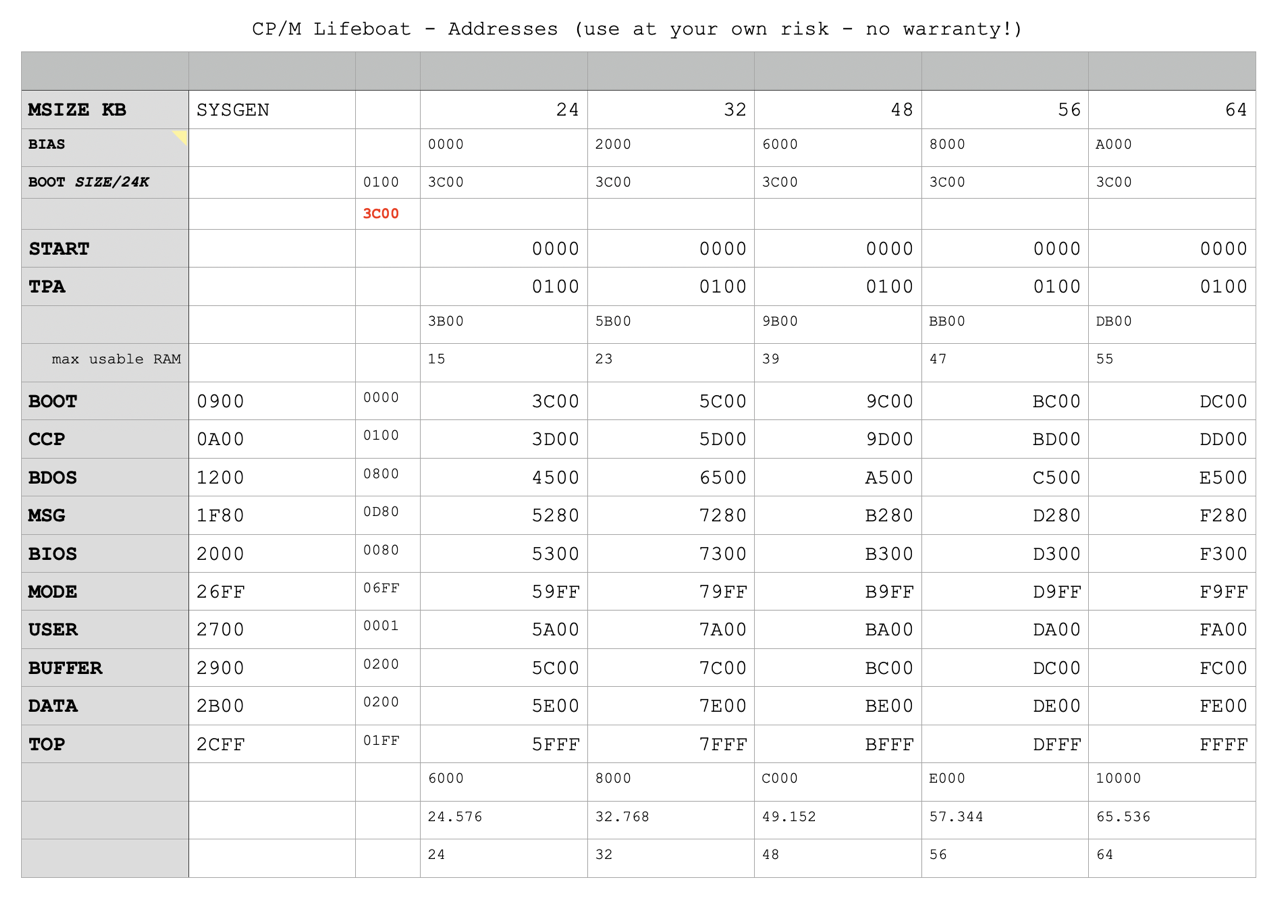
Used the range from F000 to FFFF for the memory test of my Altair 1K memory board. All very old RAM boards from 1 to 4K test very well in this range.
Alive!

(DOS, Norton Commander, Terminal)
With the following test setup, I managed to FORMAT a real HS10 floppy disk on a real floppy drive and created a real boot disk. Afterwards I connected the Tandon TM100-2 as drive A: and was able to boot the North Star Horizon from floppy disk. Awesome!
I am happy as a clam! In German: Ich freue mich wie ein Schneekönig.

(Windows 10, Teraterm, Terminal)
Furthermore, after a long search (in my fundus) and lots of testing, I managed to connect two perfect "real" floppy disk drives as A: and B:. Both have almost identical rotation speeds and the written floppy disks can be exchanged. In other words the track and head alignment are perfect. These are a TEAC FD-55BV-06 and a TEAC FD-55B-20.
I had various drives to choose from, but only these two matched perfectly. Even two almost identical FD-55BV-06 did not match. You will simply have to test this out.
Of course, I would prefer the two original drives. There have been some replacements here as well. One is a (maybe original) Shugart SA400 (single-sided) and the other is a Tandon TM100-2 (double-sided). Both are defective.
I still have two Shugart SA 400Ls from another project (DEC VT 180) that are working fine.
Update 07/02/2023: I have just switched my two Horizon's to an external floppy cabinet. It contains the DREM (A:, B:) and a Tandon TM100-2. I simply connect the external cabinet with its own power supply via an external 34p floppy cable. Why did I do this. The floppy drives sometimes show their age and since the floppy controller is very strict about the hard-sectored floppy disks and the rotation speeds, there were always problems here and there. Now I only use one external floppy station for Horizons, Greaseweazle, Kryoflux, Fluxteen.
Downloads
Here you will find all my gathered downloads for the North Star Horizon.
Information
Here you will find all my gathered downloads for the North Star Horizon.
References
- (↑) ebay sales picture
- (↑) Google Maps
- (↑) https://en.wikipedia.org/wiki/CP/M
- (↑) North Star Computers, Inc., Product Catalog, May 1980
- (↑) CP/M2 ON NORTH STAR DISK DOUBLE DENSITY - QUAD CAPACITY USER'S NOTES BY LIFEBOAT ASSOCIATES
- (↑) TECHNICAL MANUAL for Model DMB 6400 Series S-100 Dynamic Memory Module, p.14
- (↑) MICRO-DISK SYSTEM MDS-A-D DOUBLE DENSITY, 1978
- (↑) Dwight Elvey, VCF, https://forum.vcfed.org/index.php?threads/north-star-disk-data-format-horizon-vs-advantage.1241999/post-1301402
- (↑) Standard Specification for S-100 Bus Interface Devices IEEE Task 696.1 D2, 2.3.1 General
- (↑) HORIZON Computer System Manual (Double Density), 1980
- (↑) The Compass Newsletter, Vol 1, No 3, 1981, page 25
- (↑) The Compass Newsletter, Vol 2, No 4, page 6
- (↑) Mike Douglas, VCF, https://forum.vcfed.org/index.php?threads/northstar-horizon-mdc-a4-problem.64955/post-787957
- (↑) North Star, 32K RAM Board Manual, 1980
- (↑) North Star, 32K RAM Board Manual, 1980
- (↑) http://www.retrotechnology.com/herbs_stuff/d_nstar.html#stuff
- (↑) John Monahan, http://s100computers.com/Hardware%20Folder/Processor%20Technology/History/History.htm
- (↑) John Monahan, http://www.s100computers.com/Hardware%20Folder/Morrow/DJDMA%20FDC/DJDMA%20FDC.htm
- (↑) DJDMA_Diskette_Formats.pdf, unkown manual from deramp.com
My Series About the North Star Horizon
--> Go to Part 0: Information
--> Go to Part 1 : Restoration & (my) S-100 Boards
--> Go to Part 2 : Hard-Sectored Disks
--> Go to Part 3 : File and Image Transfer
--> Go to Part 4 : PROM Modification
--> Go to Part 5 : History
--> Go to Part 6 : RAM
--> Go to Part 7 : S-100 Bus
--> Go to Part 8 : Capacitors
--> Go to Part 9 : Virtual Horizon
--> Go to Part 10 : S-100 Boards