<-- Back to Part 0: Information
--> Go to Part 2: History
Restoration Project (1)
Last revision of this page: January 25, 2025
- Project (1): 005-293 - (5/19/2023)
- Project (2): 001-XYZ - (12/5/2023), PSRB-A
- Project (3): 004-670 - (3/27/2024)
- Purchase
- Cabinet
- Front Panel
- Back Panel
- PSU
- Fan
- Mainboard
- S-100 Boards
- Other Activities
- Downloads
- Information
- References
Purchase
IMSAI (S/N 005-293)
My dream was always an Altair Mits 8800 but when an IMSAI 8080 was offered for sale in Europe in April 2023, I could not resist. The seller is from Switzerland. A very nice person, I am in regular contact with him by e-mail. I also got the two Altair 1K boards from him.
The special thing about this IMSAI 8080 is that it looks almost brand new to me. Yes, the plexiglass on the front panel is a little scratched, or you can see a few marks, but from the inside it looks perfect. The purchase was a real stroke of luck.
In the meantime, I am even glad that I have acquired an IMSAI 8080. It is technically better than the ALTAIR 8800 and just looks great, really great.
And then there's the story about David Lightman and Jennifer Mack. Even in 2023, i.e. after 40 years, the topic of 1983 is red-hot and has lost absolutely nothing of its topicality. Mankind simply does not learn.


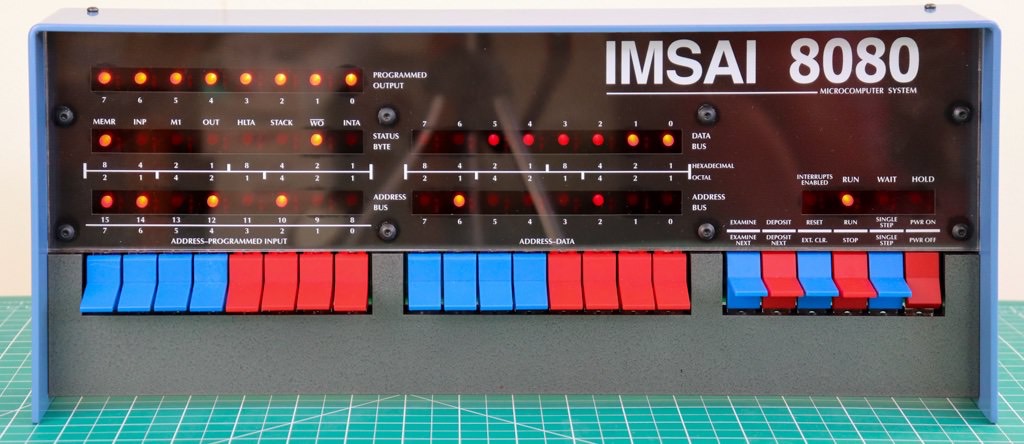
As you can see from the pictures, it is an IMSAI in the so-called elementary version, i.e. it is operated exclusively via the front panel.
In a difference from the elementary version, my IMSAI has a RAM 4A-4 (4K) memory card instead of the RAM 4A-1 with 1K.

Cabinet
[Thomas Fischer] The sheet metal was often the first thing to be assembled since it provided the sense of a "real" computer, even if incomplete. The color combination was chosen to reflect a kind of "thumbing your nose" attitude toward Bill Millard's former employer IBM. The IBM Blue cover and Charcoal Gray switch escutcheon complimented the nicely proportioned box and front panel. Constructed of 16 gauge aluminum, the sheet metal kit consisted of the base plate, back panel, front sub-panel, switch escutcheon, two card cage side panels, motherboard riser plate (which also helped stiffen the base plate), CP-A (front panel board) switch bracket, and a cable clamp for the back panel (top). Except for the IBM Blue cover and Charcoal Gray switch escutcheon, the aluminum was typically finished in either clear or light gold alodyne, depending on vendor. Alodyne is a dipping process, not electroplating.
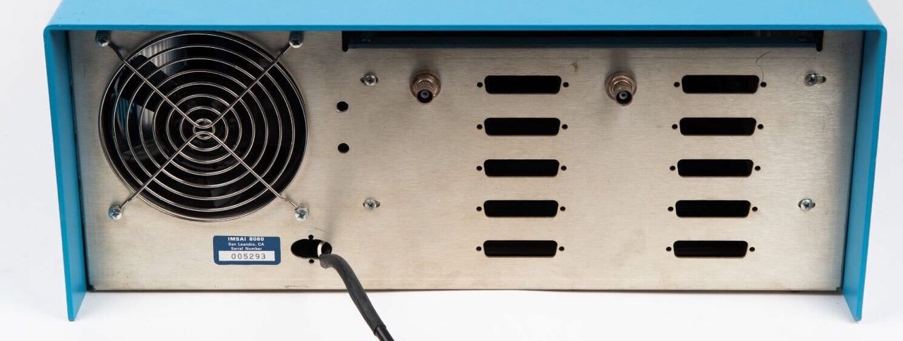
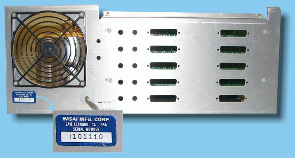
The first 100 or so units did not use threaded inserts (6-32 PEM nuts) as extensively as the later revisions did, choosing instead to employ #6 hex head self-tapping sheet metal screws to attach many of the panels together. Most notable is the rev. 1 front sub-panel which, along with the back panel, was attached to the base plate with the same sheet metal screws. The back panel featured a 4 1/2" cutout for the optional 3-blade "whisper" fan. A black plastic finger guard was provided with all units to keep debris and small mammals from entering the cabinet, whether supplied with a fan or not.
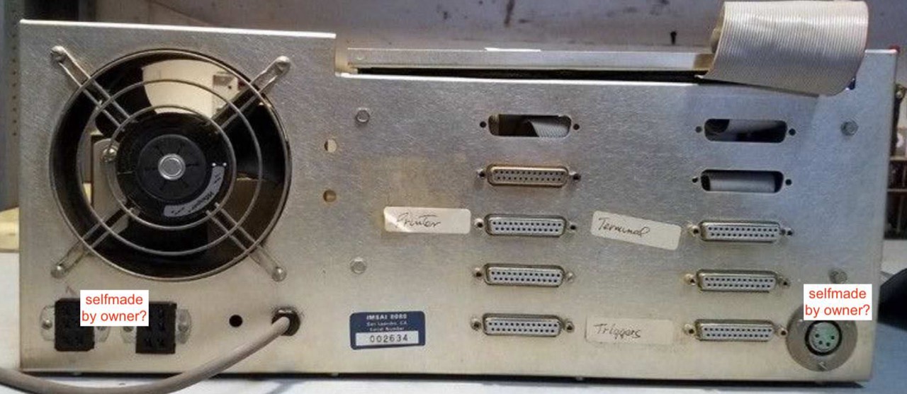
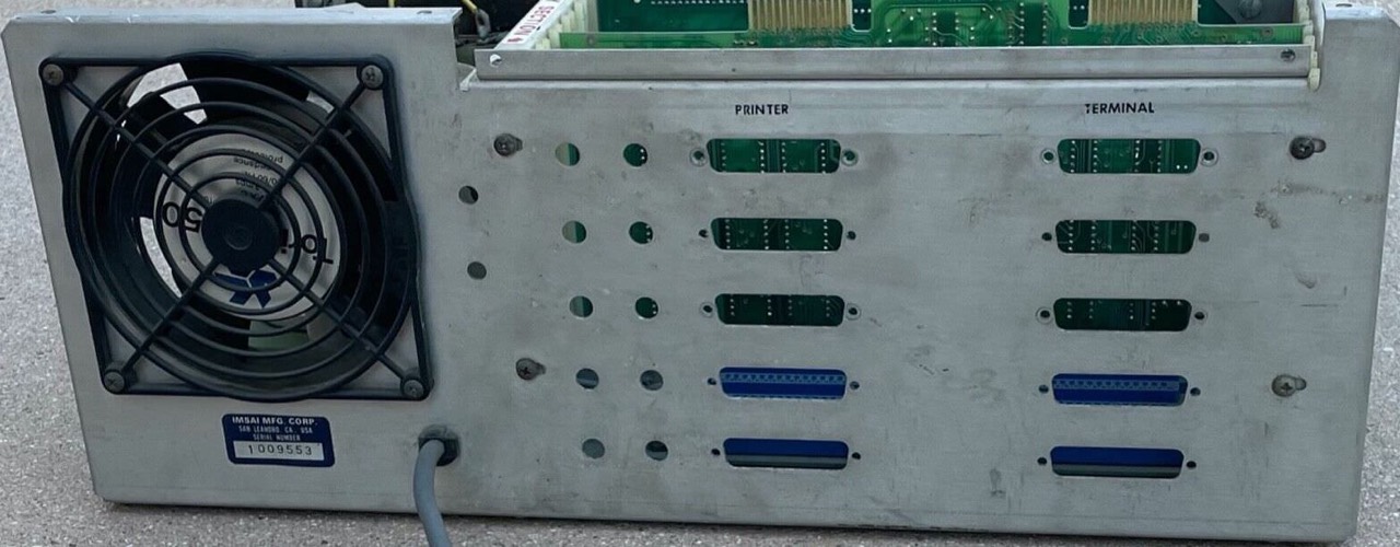
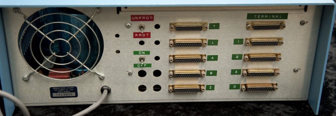
The early back panel has two 1/4" holes located to the right of the 4 1/2" fan cutout. These were intended for accessory cables, most commonly the cassette data storage interface input/output audio cables that were offered as an option. Ten DB-25 cutouts were provided for cables in addition to the cable clamp located at the top of the panel. This was provided to add versatility in cabling to peripheral devices. [18]
Color

I did a little searching on the internet. The colour IBM Blue appears in at least three different values (#1F70C1, #5A87C5, #006699). But none of the three matches exactly the colour of my IMSAI cabinet; the first colour (#5A87C5) is the most likely. IBM Blue is not IBM Blue.
Update 05/26/2023: The previous owner told me, that he has re-powder-coated the blue cover, hence the slight colour deviation. On the one hand, this is nice because the cover looks perfect, but on the other hand, it is no longer original. Now then.


According to Ross Milbourne, the IBM colour tone is RAL 5012 (Lichtblau, light blue). [12]


So much for the colour. Now it is on you.
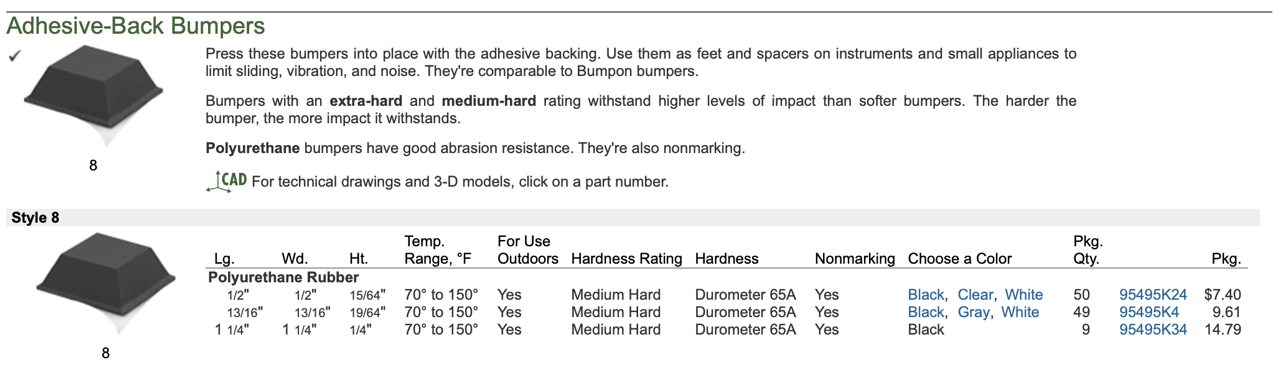
Case Rubber Feet

The case feet (front) are very worn and partly defective and feel very soft. These are probably still the original feet. As a replacement (back), I always use so-called resonance dampers from the German company Oehlbach for my enclosures (IBM, Kaypro, ...). These can be loaded up to 10kg/each and are excellent for this purpose; for my IMSAI I use 6 pieces.
Front Panel
Like the actual computer, the front panel looks very good, no dirt, no rust. The best is, all ICs are socketed. For this reason, some switches are also shortened (metal) so that the ICs can be easily replaced. Otherwise it would not be possible.
Update 06/04/2023: The front panel gives me a bit of a headache. Although it looks flawless, it doesn't work that way. This means that when an address is set and EXAMINE is pressed, the corresponding address LEDs do not light up correctly. With the help of Mike Douglas and Josh Bensadon I am trying to find the error. I have cleaned the dirty legs from every TTL (and also tested). Next I will change all/some (original) TTLs with new ones. Note: You have to watch out that some are 74LSxx and some must be 74xx because of the fanout.
[Mike Douglas] In most cases, 74LS is preferred because it is lower power than 74 and almost as fast. One exception is in an oscillator that specs a 7404 where you should probably stick with a 7404. The other situation to be aware of is when there is high fanout - which is the case with some of the front panel board ICs.
In general, LS can drive 5 standard loads or 20 LS loads. Standard TTL can drive 10 standard loads. U10 drives four standard loads which should work with a 74LS04, but they probably decided to play it safe and went with a 7404. U12 and U14 have to drive 8 standard loads, so the 7400 and 7410 are required.
Alternatively, if these loads (U1, U3, U4, U6, U7) were 74LS05, then U10, U12 and U14 could be LS parts. [15]

[Josh Bensadon] To answer your [my] question about 7400 and 74LSxx. The standard TTL and Low-power Schottky families are very similar. Their differences are mainly in the power they consume, input and output impedance and propagation delay. Ignoring power, the effects of impedance affects them in analog circuits, like oscillators. But, I believe the original designers of the CPA board used standard TTL for their faster speed. It was probably done through a trial and error basis. I believe the designers didn't have a full grasp of digital logic and just experimented until they got it working. The reason for my belief is the use of C8 on U15 pin 6. You should never have to use a capacitor on a logic line to eliminate spikes. From what I see, the 74LSxx chips should work fine on this board. [17]
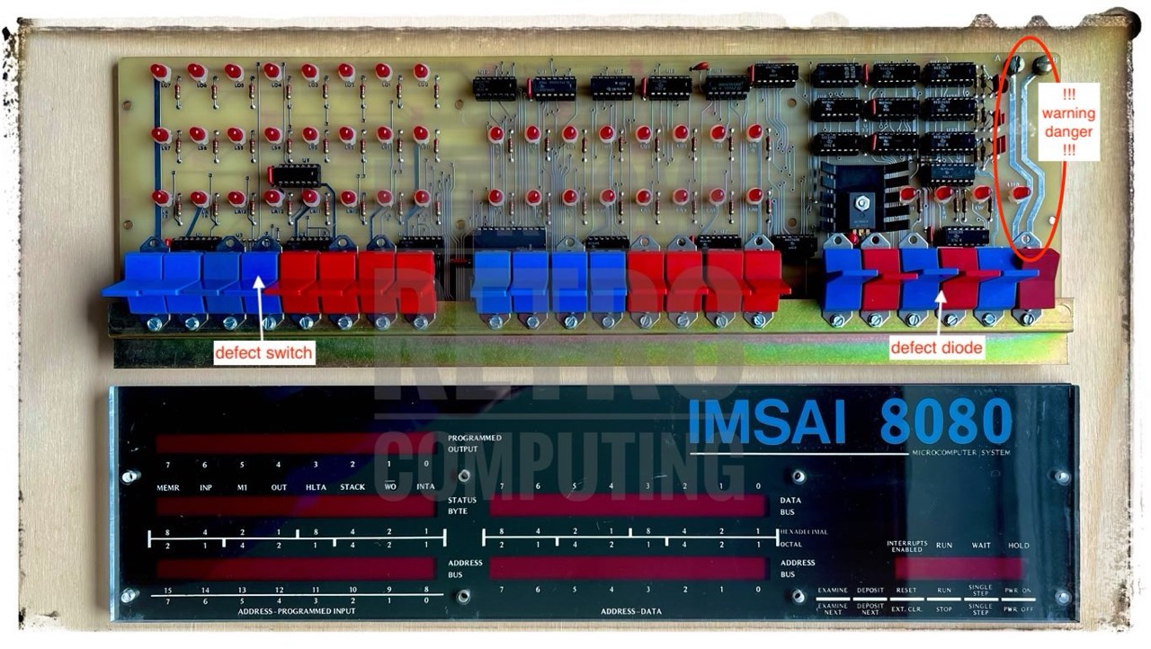
Update 06/11/2023: A first success. On the one hand, it was due to a defective switch, here SA12. I completely desoldered it and replaced it. Another fault or defect was in diode 1N914, which is located between & behind switches S3 and S4; it is very difficult to see. The lower wire had broken off at the soldering point and was loose. I have no idea how this happened. As an alternative, I simply soldered the lose wire back on. And lo and behold, the faults seem to have been eliminated.
In my experience and after consulting Mike Douglas and Josh Bensadon, the problems are often caused by the address switches SA0 to SA15. Each of these 16 switches must be checked for correct continuity or connection; i.e. switch down ... test ... switch top ... test. During this simple test, I had many connection errors because the switches were corroded on the inside. Fifteen switches worked again after switching dozens of times, I had to replace three.
If all switches, including the five on the far right, work properly, test the connection/continuity between SA0 ... SA15 and U2, see next figure.

If something is wrong here, it may be a defective 7405 (U1, U3, U5, U6, U7) or a defective conductor track.
Fortunately, all my TTL ICs are socketed. A test with my RCT tester and a possible replacement is therefore unproblematic.
Update 12/23/2023: Another moment of shock. The front panel is and remains a weak point; the contact of the switches! Only after a lot of switching is everything OK again, but I have not been able to find the actual problematic switch. Annoying! Maybe I'll have to replace all the old ones after all; but that's a hell of a job.
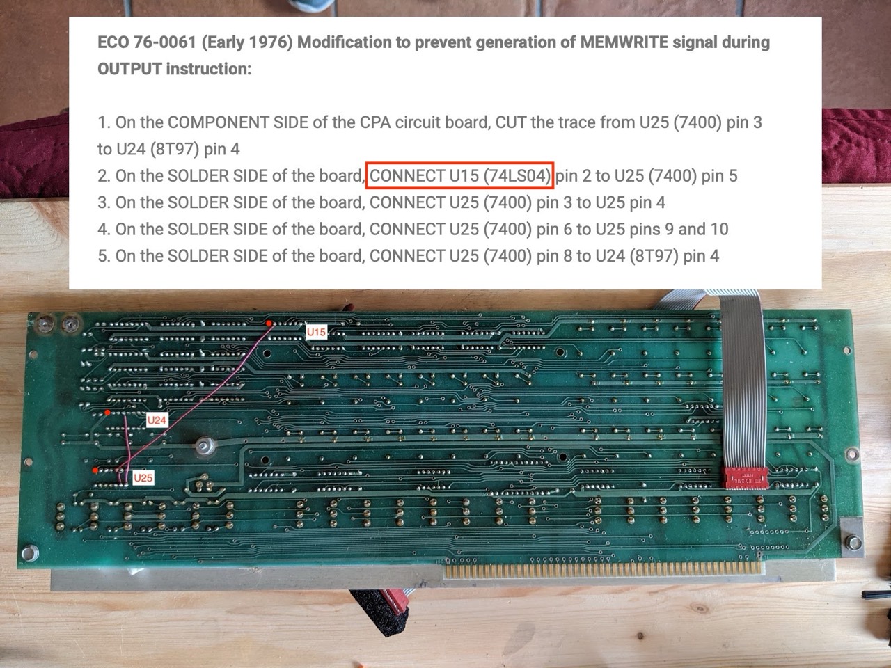
Engineering Change Orders (ECO's)
On the back a mod (ECO 76-0061) with three additional wires can be seen on the left.
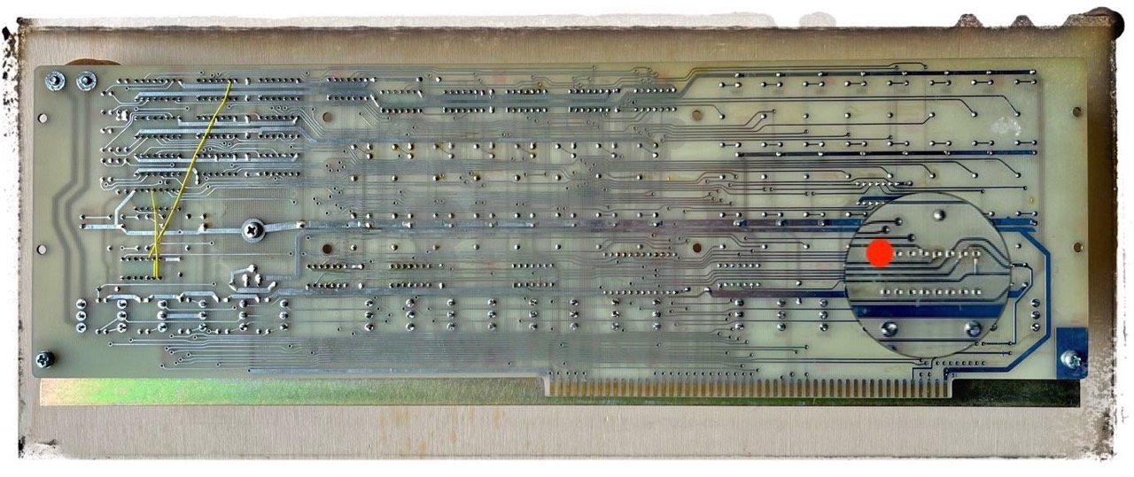
I marked the PIN 1 - cable connection to MPU board - with a red dot. Why, because my cable has a false orientation. The red marked trace belongs not to line 1 (pin 1) as one is used in the PC world!
Basically, however, U2/CPA and A9/MPU are correctly connected. A look at U2 or the schematic shows that the pins 1/16, 2/15, ... are connected to each other. The pins 9-16 on A9/MPU are a dead end!
You can follow the connection with the 16 pin flat cable very well in the two schematics by Josh Bensadon.

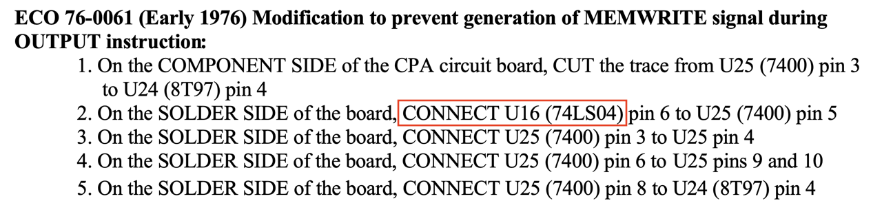
If you read this ECO carefully and look on the CPA (rev.4) at U16 you will notice that U16 is not 74LS04 but 7402! The manual also says U13 and U16 are 7402. Maybe a typo made by Fischer-Freytas Company.
To add a little more confusion, here is ECO 76-0061 but with U15!
Replacement
More information about the front panel, switches, paddles and the colours is available at Parastream Technologies.
You can still buy the switches and/or paddles at Mouser (NKK); only the color is slightly different.
I have installed three new NKK (M2012) switches so far. The new ones are much easier to switch. Whether they will last as long as the C&K (7101) switches remains to be seen.
- 7101 -> M2012 / ON-ON
- 7105 -> M2018 / (ON)OFF(ON)


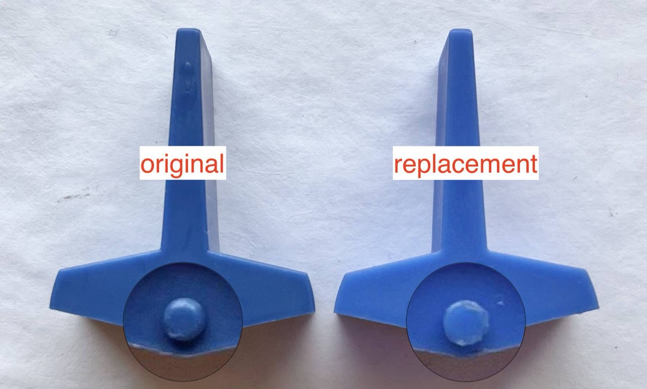
Besides the colour, you can also recognise the replacement paddles by the small round plastic knob. The original is slightly rounded at the top, whereas the replacement is flat. Accordingly, it is difficult to put the replacement paddle back into the holder. So be careful!
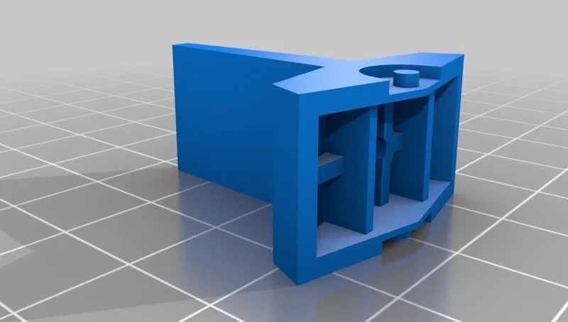
Update 12/17/2023: Making your own paddles? Here you are:
I ordered three (color) samples: blue, red and lightblue.
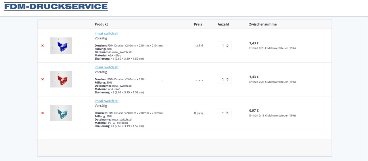
Update 01/06/2024: The 3D prints are accurate and stable and the colors fit surprisingly well (No. 2 and No. 5). The price per piece is about 1 EUR.

Here is another source, but it is a little expensive. David McNaughton (The High Nibble) actually sells switches with his IMSAI replica that look 99.9% like the original. The replica will be one of my next projects. I will probably install the NKK switches in the replica and save the others for my IMSAI. I bought the kit months ago. The switches are not 3D prints. They look perfect both in color and finish.
Update 06/16/2023: Today I had to replace two more switches (SA7, SA8). There were irregularities with the EXAMINE command. Now it works again. But attention. The switches are difficult to desolder. And it is very easy to tear out the through-plating (vias) - it looks almost like a very fine metal eyelet. Then it becomes very difficult! So watch out and work very calmly.

But even now, my IMSAI behaves like a cranky and grumpy old man. I often have to switch it on and off twice before STOP and RESET work. Somehow there is still a little bug in there! The diode?
Update 06/17/2023: Yes, the little culprit was the diode 1N914 at CR1. I had already suspected this diode because it was originally torn off and I had simply soldered it back in. The replacement arrived today. So I carefully unsoldered it and soldered it in a mad fumble. The little beast is located directly under and between switches S3 and S4. But it was worth it. The CP-A now works stably.

But what makes me a little bit suspicious is the fact that the old diode has exactly the same forward voltage as the new one, namely 0.6V. This value can also be found in the data sheet. The other way round of course 0V.
But I can definitely say that the front panel works better after the replacement. Before, I always had to switch on and off twice and STOP and RESET only worked correctly the second time. And that every time.
Now, I switch it on and everything is perfect straight away. Before, all 8 DATA LEDs always lit up. Now it's one or the other DATA LED. Now, the first green LED on the 4K board lights up immediately, which was not the case before.
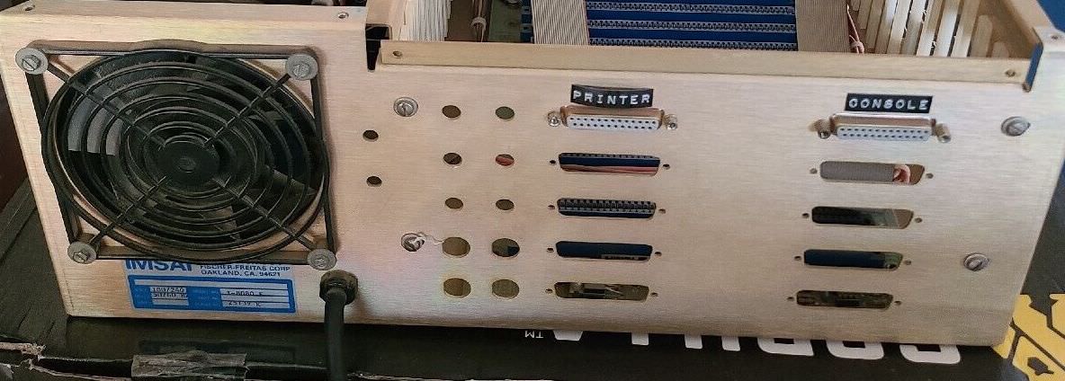
Back Panel

Power Supply Unit - PSU

If you want to bring an old S-100 computer, such as an Altair, IMSAI, SOL, Horizon, ... back to life, you should definitely start with the power supply. By this I mean both the conversion from alternating current to direct current, as well as the subsequent forwarding of the current to the mainboard and the correct power feeding of the individual S-100 connectors (pin 1, 2, 51 and 52). Look carefully at the traces on the underside of the mainboard. With my two Horizons, the -18 V line was defective in many places, i.e. burnt out! So watch out.
Basic setup: Power grid 230V/50Hz --> isolating transformer 230V --> variable transformer (variac) --> IMSAI PSU (max. 110V, 95V are sufficient in my case)
What stands out immediately? Until now, I only knew the so-called switching power supplies. Here in the IMSAI, however, a transformer power supply is installed. Simple in design, incredibly heavy, consumes a lot of power (even in idle mode) but it lasts (almost) forever.
The AC voltage from the mains is reduced to a lower value via a large transformer. This is followed by rectification of the AC voltage to DC voltage. For a "smooth" voltage, the energy is buffered via capacitors. [8]
And I thought the power supply unit on my North Star Horizon was big and heavy. But this power supply is the ultimate!
Note: I placed the fan temporary on the outside for a better overview and manageability.
Transformer
My PS-C 28 uses the Tranex 4-3751 transformer (110-120 volts AC, 60 Hz, single phase, max. 500 VA).
Now the question arises whether a 60 Hz transformer can be operated at 50 Hz (in the European power grid) without any problems. The answer is yes, if ... but read for yourself.
Can we operate 60 Hz designed transformer at 50 Hz?
We can operate a 60 Hz designed transformer at 50 Hz. However, the other performance parameters need to check. The flux in the transformer core depends on the voltage and frequency of the supply voltage. First, let us see how the flux is related to voltage & frequency.
From the above equation [not shown here], the flux is proportional to a volt per hertz and inversely proportional to the frequency.
Thus, if we keep the V/f ratio constant, the flux remains constant. We assume transformer rated voltage 400 volts, and frequency 50 Hz.
The flux in the transformer: Φ∝V/f = 400/50 = 8
Now, if we operate the transformer at 60 Hz, keeping the voltage constant (400 volts), then the flux in the transformer is: Φ∝V/f = 400/60 = 6.66
The flux in the transformer reduces with the reduction of frequency. The transformer can not be operated above its rated flux density because it causes heating. Thus, it is possible to operate the transformer at a lower flux density.
However, we need to look at another effect of flux reduction in the transformer. The secondary voltage also decreases with the decrease of flux.
The flux reduction of about 16.75% cause voltage to reduce by 16.75%. If the output secondary voltage is within the operating range of the equipment to be connected to the transformer, then we can operate the 50 Hz transformer at 60 Hz. [21]
Other voices from forums come to the conclusion that these two statements above actually only apply to large transformers. These small ones, on the other hand, do not come into the saturation range and function well at 50 and 60 Hz. But as I said, you have to come to your own result and decide for yourself.
For me: 115V x 0.833 = 95.8V. This is even very good, because my power supply delivers DC output voltages of 8V or 16V at 95V AC input voltage (with no load). This means that the 5V 7805 regulators do not have to "work" as much and generate less heat. This concerns my front panel in particular.
I use a variac and yes, a variac wastes energy, but my solar system produces up to 10 kW peak and I have a 10 kW storage battery!
You want to replace your transformer with a custon made brand new one. Have a look at ETE in the UK.
Step 1
Today (05/20/2023) I put the power supply into operation for the first time; without frontpanel. I have connected a variable transformer. As loads I have connected two old 12V fans; one on the +8V and the other on the +16V line. And so the original power supply runs at first with about 80V input voltage instead of 110V.

Exactly at 80 V, the (12V) fan on the +8V line also begins to rotate and the (12V) fan on the +16V line now has exact +12V. I now operate as follows: slowly increase AC current to 80V, then run for 5 minutes, then power off for 2 minutes, ...
As with my Horizon, the IMSAI requires max. 95V AC input to get -16V, +16V and +8V DC output voltage (with no load). With 110V AC input the output (with no load) is 18,1V and +9,7V. This all looks perfect. I will watch and report the behaviour under load.
Update 06/17/2023: With load (two S-100 boards) I had to increase the input voltage to 100V AC to get -16V, +16V and +8V DC output voltage.
Step 2
In the next step, I will then check the voltages on PINs 1, 2, 51 and 52 on each S-100 connector (21 of them). ... some days later ... I have checked all, everything is fine.
Step 3
I renewed the power cable, the cable gland and replaced the old luster terminal (screw connection) with three modern crimp connectors. I then reattached the fan with self-locking screws and fixed the fan cable. Now everything should be perfect; nothing moves, nothing rattles.

Step 4
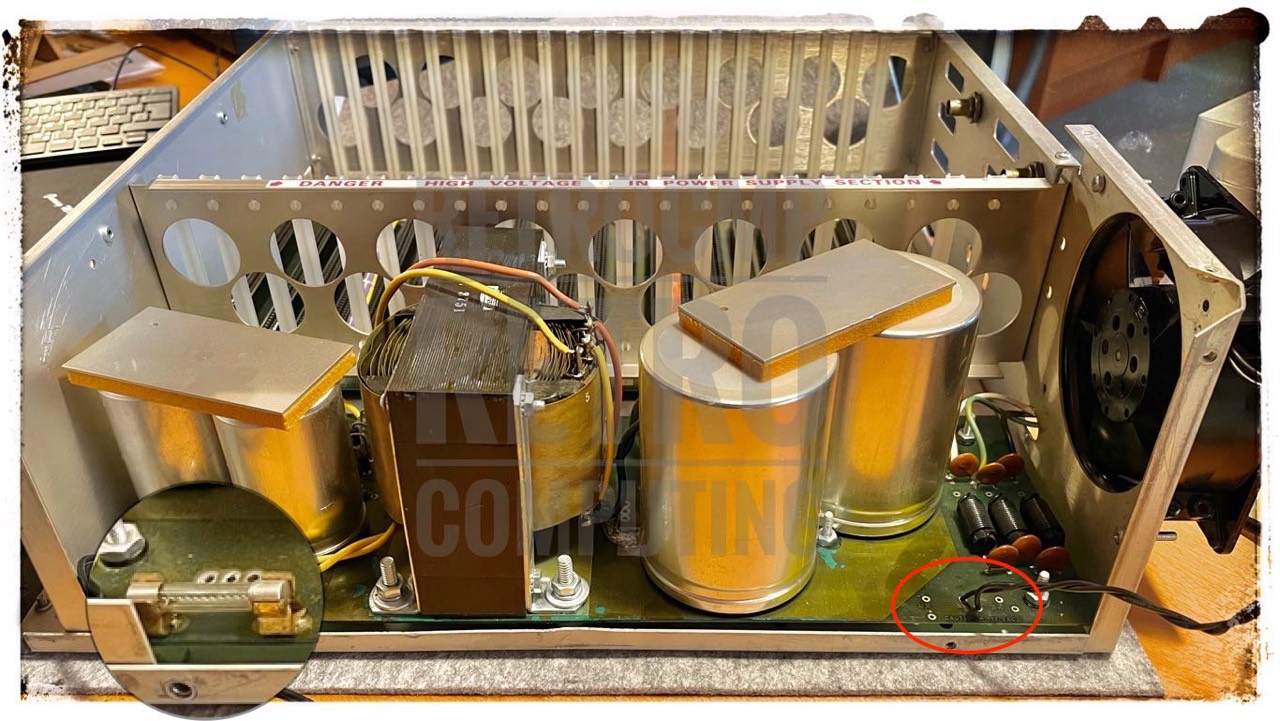
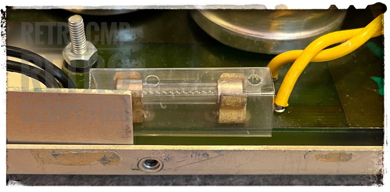
I almost forgot one very important issue: the fuse. Placing it so close to the edge of the housing is actually grossly negligent. I secured it with a piece of an IC tube. Now nothing can happen!
Capcitors
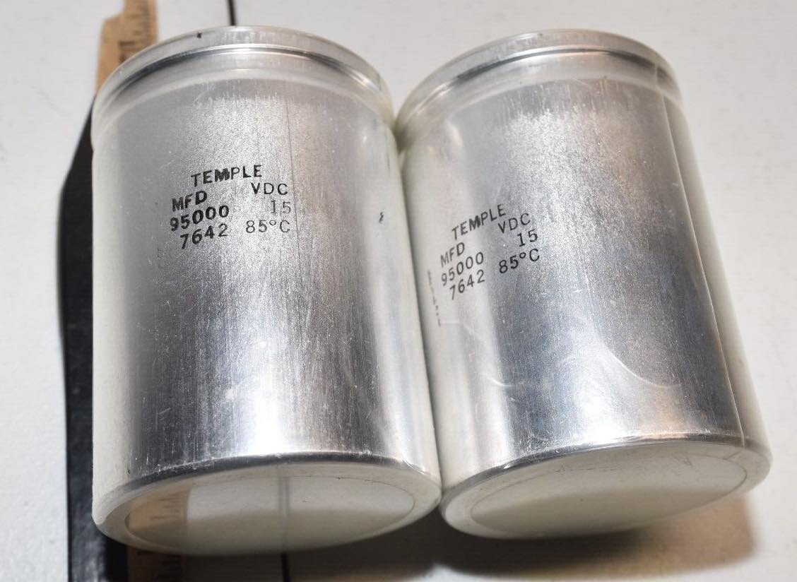
My IMSAI uses two large capacitors - in parallel circuit - on the +8V line and one smaller each on the +16V and -16V line; the manufacturer is Temple. I had a bit of luck and was able to buy C0 and C1 (used) on ebay US for $10 both. They are still on the road (06/2023). I will report ...
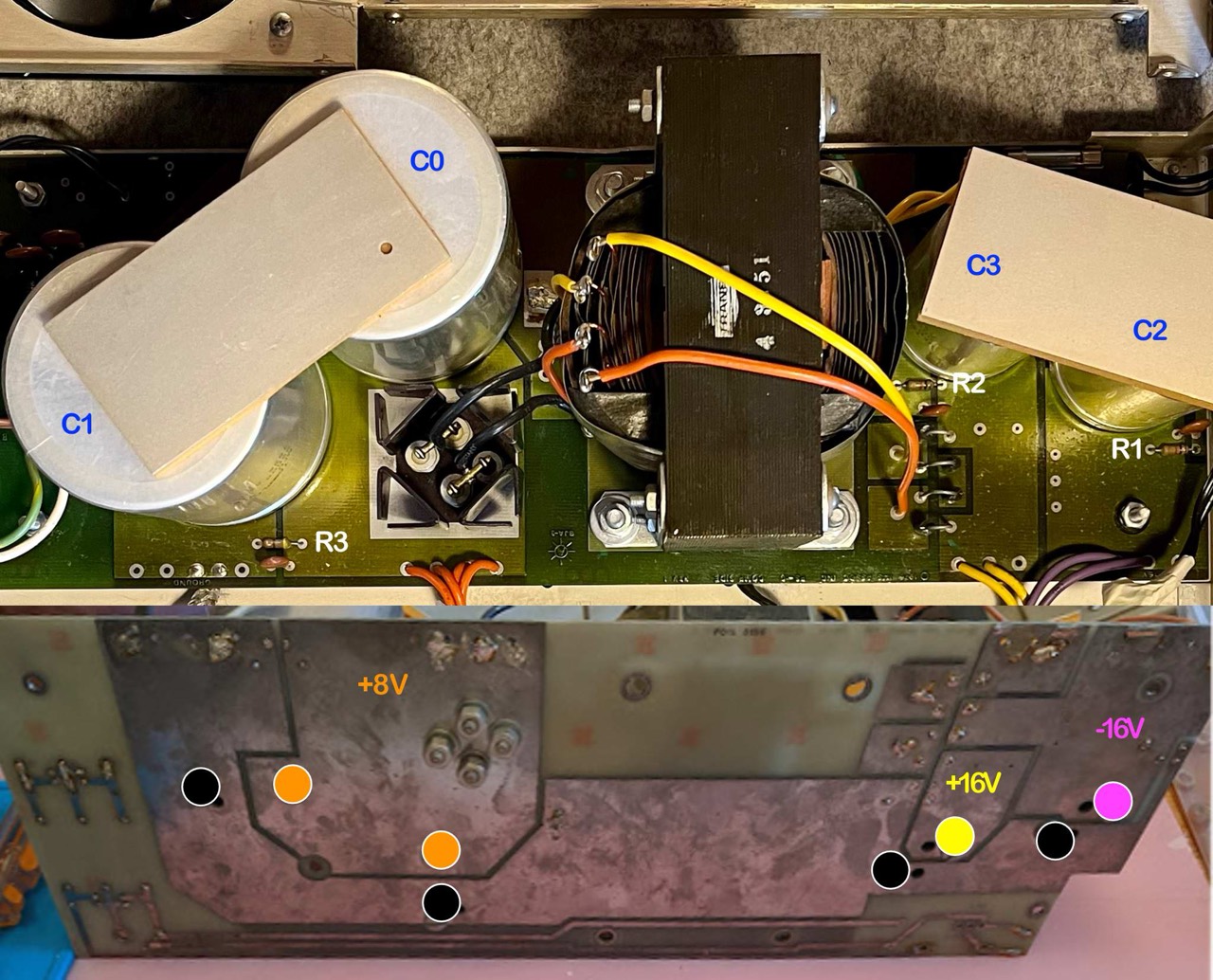
- C0, C1: +8V line:
15V, 95,000 uF (MFD)
75 x 103 mm
datecode 7636
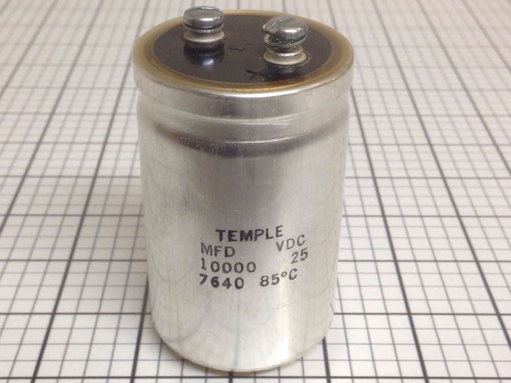
R3: bleeding resistor 470 Ω - C3: +16V line:
25V, 10,000 uF (MFD)
50 x 77 mm
datecode 7636
R2: bleeding resistor 1.0 kΩ - C2: -16V line:
25V, 10,000 uF (MFD)
50 x 77 mm
datecode 7636
R1: bleeding resistor 1.0 kΩ
I have checked the three bleeding resistors (R1, R2, R3), they measure exactly 1.0 and 0.47 kΩ. They work fine after switching off, the voltage on the three DC lines goes to zero very quickly. That is exactly what they are there for.
If I had wanted to check the four capacitors properly, I would have had to remove the entire power supply board with everything on it. With my two Horizons this was very easy because I could simply disconnect the capacitors. The result was that all the capacitors worked perfectly even after forty years. For this reason, I simply had confidence in the IMSAI capacitors.
This issue is discussed by Ross Millbourne in his quite excellent blog about the restoration of an IMSAI 8080 for the Centre For Computing History at Cambridge, UK. You must read this blog! He also describes the reforming of old and large capacitors!
Reactivating Large old Capacitors
Update 06/27/2023: Here are my personal steps in reforming old capacitors. I have created a separate chapter in my Northstar blog: Reforming large old capacitors.
PSU Variants
Fan
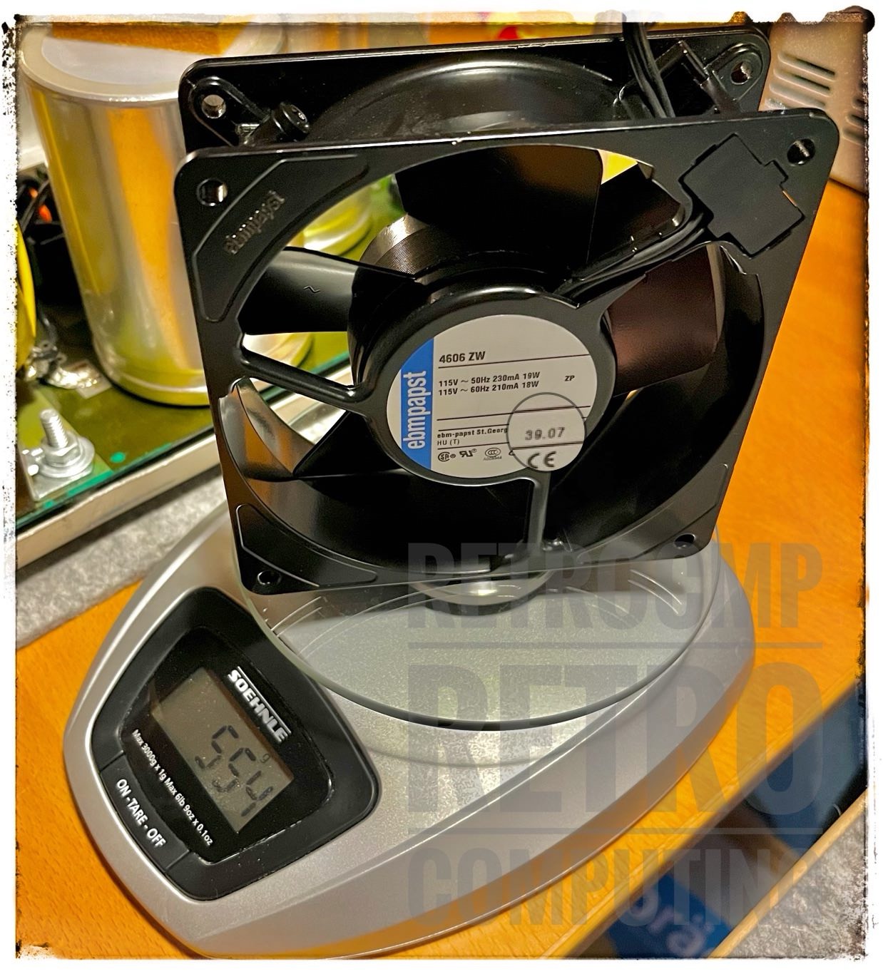
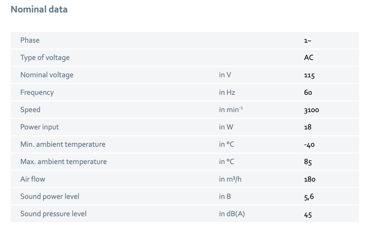
Built for eternity, everything is full metal! Made by ebmpabst, quality from Germany.
This is not the original fan. The original one was replaced by the previous owner. The date code is 39.07; it is still sold for 53 EUR in Germany.

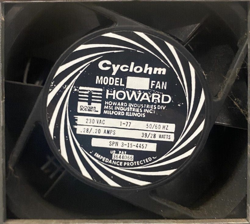
Accoding to the owner, this fan is full metal too. This could be an original fan, although the date code 3?.80 is also a little strange.
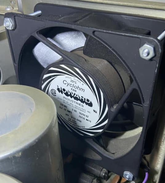
Howard Industries 3-15-2450 Cyclohm Fan, 115VAC 60Hz, 0.21/0.19A, 19/16 Watts
The fans from Howard Industries (Cyclohm) were also used in the Altair.
Switch
And while I was at it, I installed an extra switch for the fan. The hole required for this is already there and, appropriately enough, is right next to it. A second hole is also available. I always use special crimp connectors (WAGO 221) for the cable connections.

Mainboard
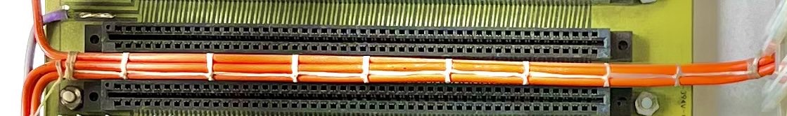
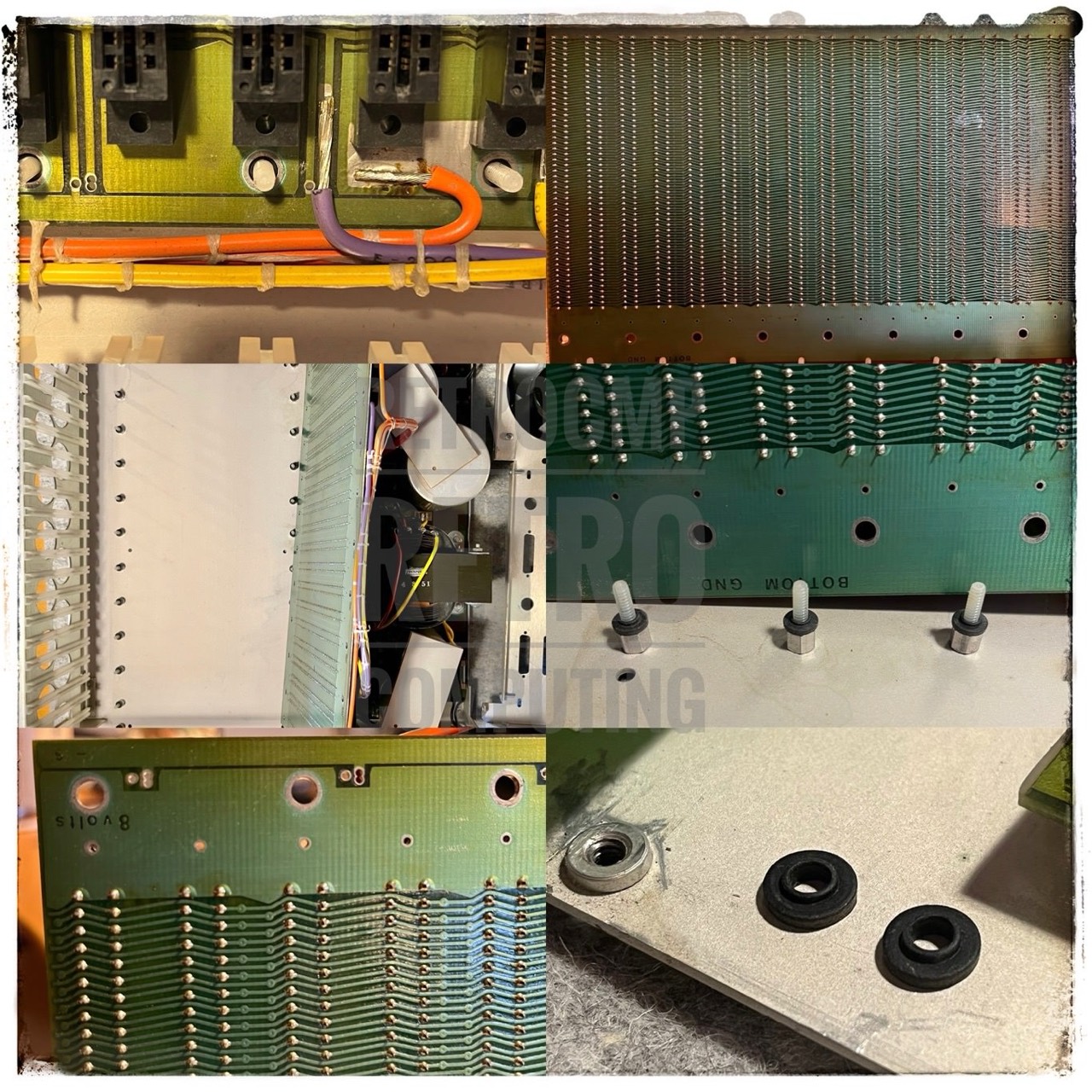
The mainboard has a completely simple design. The only thing that bothers me is that the various power connections are soldered and not with plugs like on the N* Horizon. This makes it impossible to remove the mainboard, which is too bad.

The best thing are the "cable ties". Not the modern plastic loops, but the individual cables are professionally tied together with a waxed flat thread. Simply ingenious.
[Thomas Fischer] The first IMSAI 8080 units and kits shipped with either an EXP-6 (standard) or EXP-10 motherboard (optional), depending on what was ordered. Only two sockets (with two nylon card guides each) were supplied with the basic machine. Additional sockets with card guides were optional. The EXP-6 was standard, while EXP-10 and the EXP-4 were optional choices, depending on the customer's anticipated requirements. EXP is a contraction of "expansion", and the number indicated the socket or "slot" capacity of each. By early spring of 1976, the EXP-22 became available and, by September of 1976, became the standard offering.
For the most part, all IMSAI circuit boards shipped in December of 1975 and early 1976 were not solder-masked. As old stock of the first revision boards was used up and new stock ordered, masked boards became standard. Prototype boards were not solder-masked except for some early and mid-1977 exceptions.
IMSAI offered a terminated motherboard beginning in Spring of 1977 with the introduction of the VDP-80 (Video Display Processor) which used an EXP-7 (7 card slots), and the EXP-10 used in the 80xx and VDP4x series machines. Termination of address and data lines was provided with 220/330 ohm resistors referenced to regulated five volts, a standard industry practice at that time. In 1981, Fischer-Freitas Corporation entered into agreement with Morrow Designs to offer George Morrow's 20 slot terminated motherboard as an option. We only sold about 20.
The second (from the front) slot of the EXP was seldom usable since there was inadequate clearance between the front sub-panel and components of the second slot board. IMSAI specified Texas Instruments gold-plated phosphor-bronze contacts for the S-100 sockets used in motherboards (and board sockets where used). Since all board contact fingers heavy gold plated over nickel (for strength), contact was usually adequate and seldom caused problems. The exception to this came about from the unfortunate choice of service personnel and customer alike using rubber erasers to clean the gold contacts. Eventually the gold would be worn away- even the nickel plating, thus exposing the copper as a contact point. Oxidation and corrosion would then rapidly aggravate flaky operation of an otherwise reliable system. High humidity and salt air environments made for trying times for Customer Support! [18]
S-100 Boards
Below you will find all my S-100 (IMSAI) boards (here are my other S-100 N* Horizon) boards.
IMSAI MPU-A
The IMSAI MPU-A 8080 CPU card was what the original Altair equivalent card should have been. It was made on a better quality board with proper gold plated edge connectors and a cleaner well spaced trace pattern. Clearly resistor packs were still not that common and nothing but the absolute essentials to put the 8080 signals on the bus were present. It was meant to be a direct copy of the Altair board although it did use a 16 pin connector on the top right hand corner to interface to the front panel instead of Altair Molex connector. Clock and strobe signals were generated by a 8224 clock driver. [2]

In addition to the MPU-A, there is also an MPU-B board. [22]
The most valuable thing about this board is the white/golden Intel C8080A processor, although in my case the label is almost unreadable. I think a working C8080A in good condition is currently (05/2023) priced at 150 EUR and above. With the exception of the processor, the ICs are unfortunately not socketed. The connection for the front panel is located at the top right.
Next you see a PCB reproduction by Gary Kaufman; with socketed IC's, easy to test or change. Note: There are missing parts top left but the card works, see next.
The ebay seller tpkirkp notes: "These kits now have 8T97 Bus driver chips. Kits now have a red IC socket for the front panel interface cable. With the crystal type provided in this kit, L1, C4 and C17 are not necessary, ...

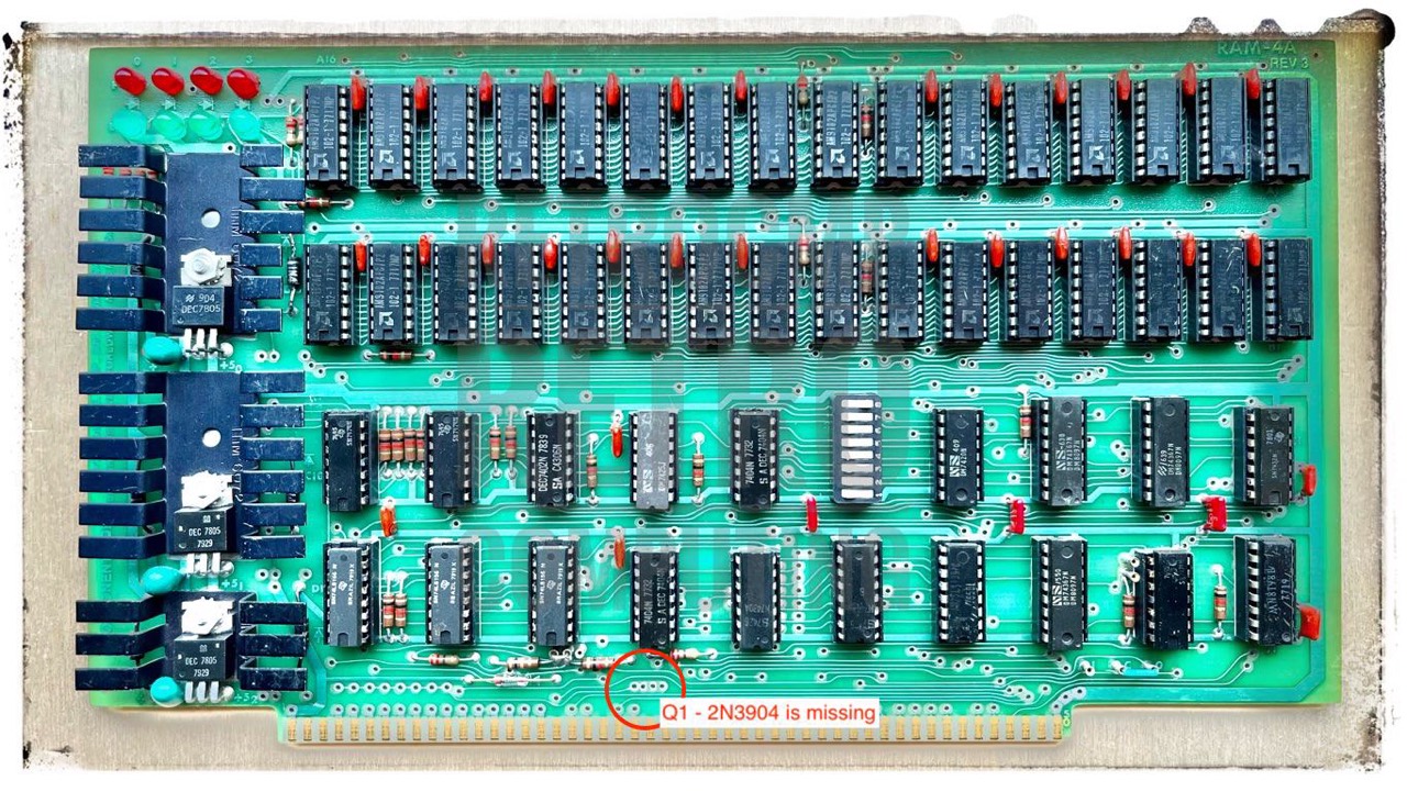
IMSAI RAM 4A-4 - Static RAM - 4 KByte
This board is equipped with 2 x 16 AM9102APC/P2 (1,024 x 1 bit, 500 ns). The almost identical card is also available as RAM 4A-1 as a 1K version, see below. On my board, all ICs are socketed. But that is not always the case!
The transistor Q1 (2N3904) is missing (maybe has never been installed). According to Josh Bensadon Q1 is only used for interrupts. [19]
Four red LED's are provided to indicate the protect status of each of the 1K blocks of memory.
Four green LED’s are also provided which illuminate when their respective block of memory is addressed. This can be easily tested with the front panel address switches. EXAMINE the addresses 0000h, 0400h, 0800h and 0C00h and the corresponding LED will light up; with the board in the first 4K block.
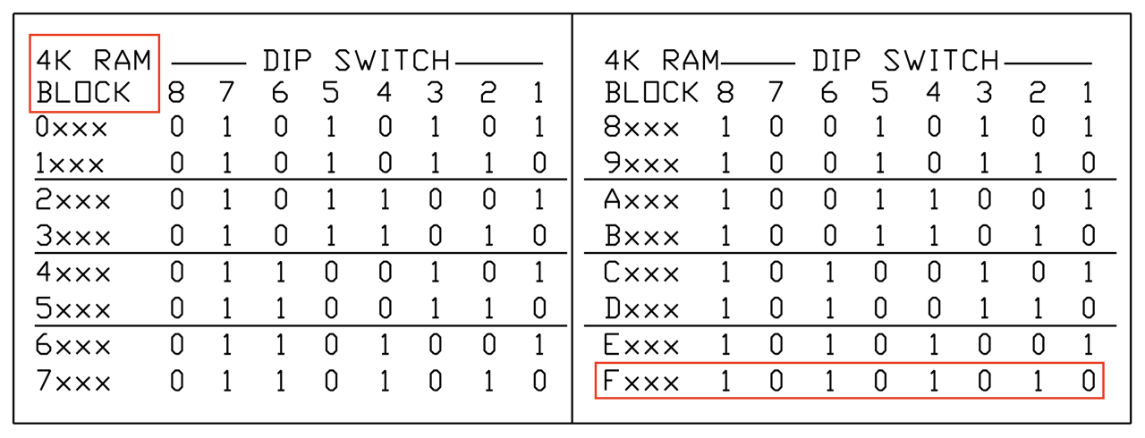
DIP switch: left pressed is ON (1) see no. 8, right pressed is OFF (0) see no. 1 to 7. Yes, the handling of these dip switches takes a lot of getting used to, especially because there are several variants.

- x000-x03FF: A16=bit0 to A09=bit7 (RAM 4A-1 board)
- x400-x07FF: A08=bit0 to A01=bit7
- x800-x0BFF: B16=bit0 to B09=bit7
- xC00-x0FFF: B08=bit0 to B01=bit7
Replace x with the corresponding block (0 ... F); dip switch C5
Testing the RAM-4A on my North Star Horizon with MEMR (Rasmussen memory test) on Youtube.
For this, I have placed the 4K address range of the RAM-4A at the very top of the 64K memory range (Fxxx: F000-FFFF). This area is generally not occupied on the North Star Horizon. The PROM on the CPU was typically placed at E000 and the micro disk controller occupies E800-EBFF. Everything that comes after that (Fxxx) is therefore not usable for CP/M programmes. For the memory test, however, this unused area is excellently suited.

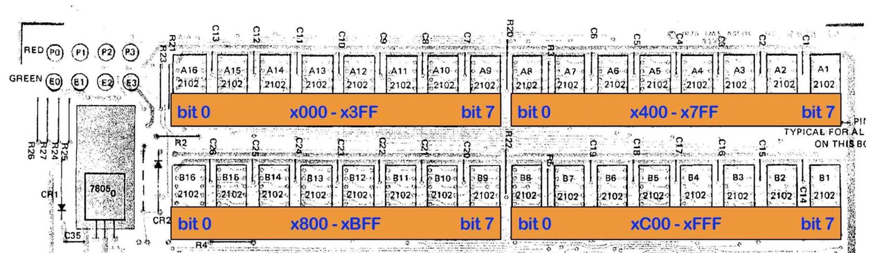
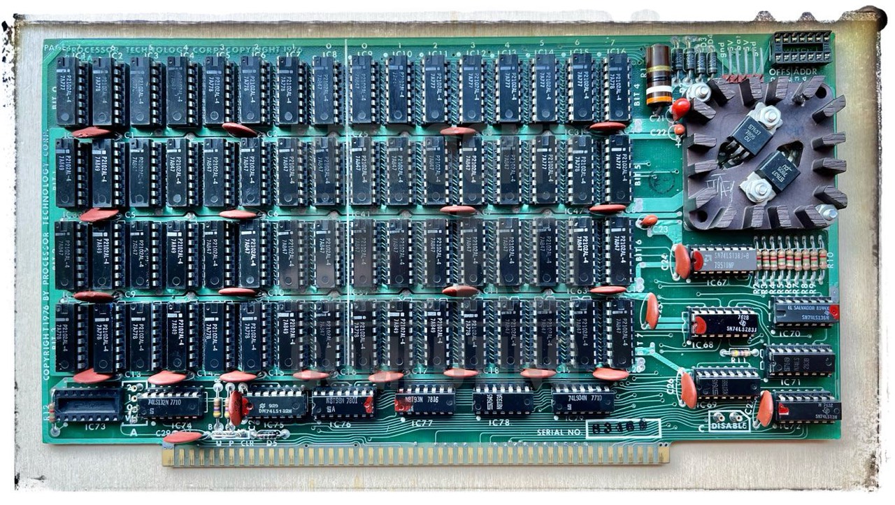
Proc Tech - Static RAM - 8 KByte
This was an early non-IEEE 696 S-100 RAM board from about 1976.
Processor Technology [Proc Tech] was founded by Gary Ingram and Bob Marsh, mutual friends in Berkley CA who had been attending the early Bay Area Homebrew Computer Club meetings in the mid 70's. At the meetings they heard many complaints from members about the early Altair 4K Dynamic RAM kits and their unreliability. They decided to build and market a 4K static RAM kit for the Altair themselves. [17]
This board is equipped with 4 x 16 Intel P2102AL-4 (1,024 x 1 bit, 450ns). According to the manual it is plug-in compatible with the Altair 8800 (and IMSAI 8080); the PINs 20 and 70 are not grounded. Already the access speed of 450ns shows that this board is only suitable for the old 2 MHz computers like Altair 8800 and IMSAI 8080.
The 2102 RAM ICs used on the 8KRA board are arranged as 1024 by 1 bits. Eight of these chips are "paralled" to drive a storage of 1024 8 bit words or bytes. There are eight of these groups on the board driving a total board storage capacity of 8192 (8K) 8 bit words. These eight 1K blocks can be referred to as eight 1K "pages" of RAM.
Basically, the two 8K boards (IMS 8K and Proc Tech) are similar. Both use the same RAM ICs (2102, 1,024 x 1bit) and thus also the same number (2 x 32). Only the actual arrangement of the 8 x 1K pages on the PCB is different. However, this only comes into play if you have to find a defective RAM IC.
The board is heavy and difficult to press into the Horizon S-100 slot. All ICs are socketed and therefor easy to change.

As you can see in the following table, the start address can be set on every 1K boundary in the 64K space! In the early days, this small-scale RAM addressing was still useful and necessary. Later, it was divided into 4K or 8K steps only. My IMS 8K board can only be set to 8K boundaries!

Next is the RAM IC calculation to find a bad IC. A RAM tester is not much use with these old boards, because you don't want to test all 64 because of one or two defective ICs.
PAGE    7  6  5  4  3  2  1  0   0  1  2  3  4  5  6  7

BIT 0  70 60 50 40 30 20 10 00  04 14 24 34 44 54 64 74  BIT 4
BIT 1  71 61 51 41 31 21 11 01  05 15 25 35 45 55 67 75  BIT 5
BIT 2  72 62 52 42 32 22 12 02  06 16 26 36 46 56 66 76  BIT 6
BIT 3  73 63 53 43 33 23 13 03  07 17 27 37 47 57 67 77  BIT 7

Address range: 0000 to 1FFF, 8K
0000 - 0FFF: 4K - 4 x 32 ICs
1000 - 1FFF: 4K - 4 x 32 ICs

---------------------------------------
0000 - 03FF / ICs 00 - 07

bit 0       / 00
bit 1       / 01
bit 2       / 02
bit 2       / 03
bit 4       / 04
bit 5       / 05
bit 6       / 06
bit 7       / 07
---------------------------------------
0400 - 07FF / ICs 10 - 17

bit 0       / 10
bit 1       / 11
bit 2       / 12
bit 2       / 13
bit 4       / 14
bit 5       / 15
bit 6       / 16
bit 7       / 17
---------------------------------------
0800 - 0BFF / ICs 20 - 27

bit 0       / 20
bit 1       / 21
bit 2       / 22
bit 2       / 23
bit 4       / 24
bit 5       / 25
bit 6       / 26
bit 7       / 27
---------------------------------------
0C00 - 0FFF / ICs 30 - 37

bit 0       / 30
bit 1       / 31
bit 2       / 32
bit 2       / 33
bit 4       / 34
bit 5       / 35
bit 6       / 36
bit 7       / 37
---------------------------------------
1000 - 13FF / ICs 40 - 47
...
Other Activities
After a break of more than half a year on my IMSAI project, I now want to try to get it running properly this winter. The problem so far is the missing SIO card. In the meantime I have bought two CompuPro Interfacer1.
Question: Does everything still work as it did 6 months ago? The problems were caused by the address switches (SA0-SA15), among few other things. No, even now the remaining old switches are causing problems. There does seem to be a contact problem with some of them. So switch, switch, switch, back and forth 50 times; it works again.
But replace all the remaining ones? I have all the switches as replacements in stock. But desoldering is a tedious job, even with a desoldering gun. The three contacts of the switches are very tight and there is the risk of tearing out the through-hole plating; this happened to me twice; not good.
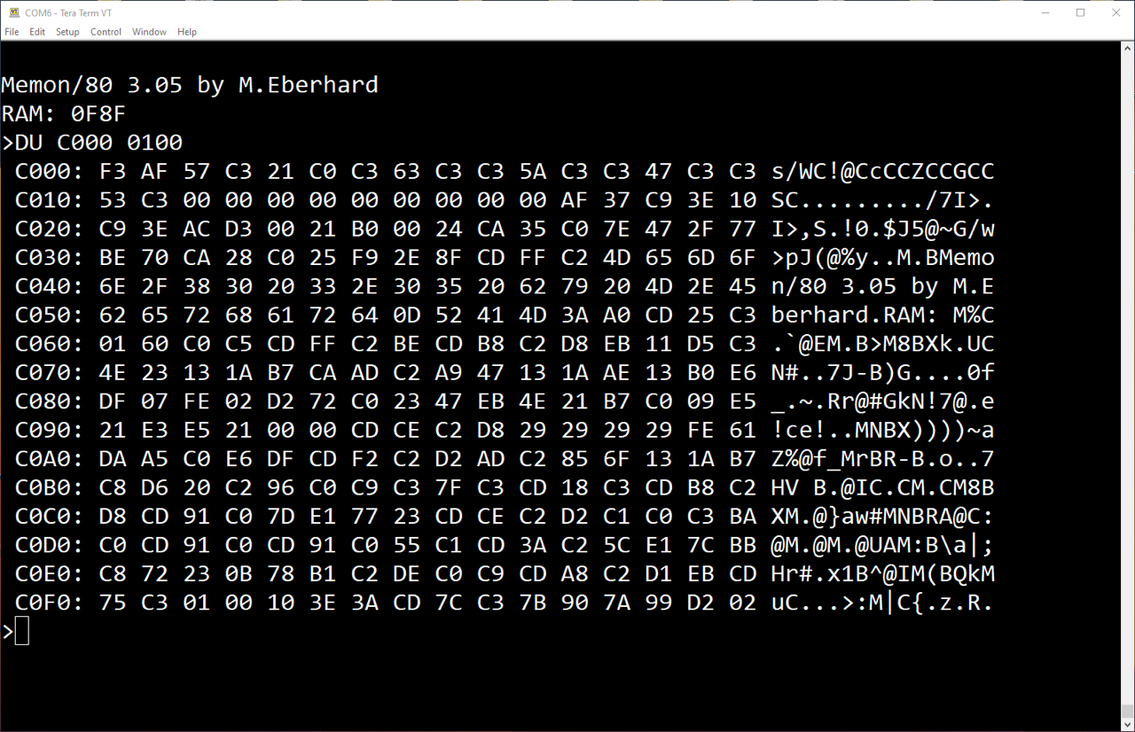
Monitor Program
First I need a good monitor program. I have a properly working Cromemco Bytesaver, so this should not be a real problem. You can find the appropriate monitor program on Mike Douglas' server. It is called MEMON/80 and was developed by Martin Eberhard.

Initially, I only need one console for the monitor, i.e. the SIO card must work; the Interfacer1 in this case. Next you see the minimal settings, the rest will come later. More must not be set, otherwise the code will not fit on a 2708 EPROM. The first three settings are mandatory as they are always required, but no transfer port, no FDC!
MEBASE  equ   0E000h  ;Base address of Memon/80 code, same as my N*
CPUMHz  equ   2       ;Integer CPU speed in MHz
ROM2K   equ   FALSE   ;set to 1K 2708

CIFAC   equ   TRUE    ;Compupro Interfacer 1 (Port A or B)
CBASE   equ   000h    ;Console Port base address
Making the HEX file with ASM on my virtual IMSAI (8080-SIM by Udo Munk). Attention! The IBM 3740 floppy disk format (SS, SD) is used here. Only 241 KByte fit on one floppy disk! For this reason, the MEMON80 file must have the virtual extension BBZ. No PRN file may be written because there is simply no space on the floppy disk.
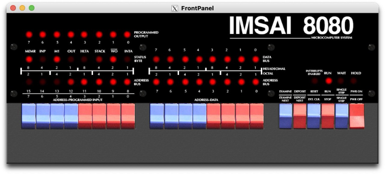
FrontPanel Simulator by John Kichury
% ./cpm22.sh

 #####    ###     #####    ###            #####    ###   #     #
#     #  #   #   #     #  #   #          #     #    #    ##   ##
#     # #     #  #     # #     #         #          #    # # # #
 #####  #     #   #####  #     #  #####   #####     #    #  #  #
#     # #     #  #     # #     #               #    #    #     #
#     #  #   #   #     #  #   #          #     #    #    #     #
 #####    ###     #####    ###            #####    ###   #     #

Release 1.37, Copyright (C) 1987-2021 by Udo Munk
IMSAI 8080 Simulation Release 1.18,
Copyright (C) 2008-2021 by Udo Munk & 2018-2021 by David McNaughton

...
...
...

54K CP/M 2.2 VERS B02

A>dir b:
B: MEMON80  ASM

B>a:asm memon80.bbz
CP/M ASSEMBLER - VER 2.0
FBF8
013H USE FACTOR
END OF ASSEMBLY

B>dir
B: MEMON80  ASM : MEMON80  HEX
B>a:stat *.*

 Recs  Bytes  Ext Acc
 1800   225k   15 R/W B:MEMON80.ASM
   23     3k    1 R/W B:MEMON80.HEX
Bytes Remaining On B: 13k
(on my IMSAI 8080 with RAM-4K)
You need more information on MEMON/80?
SIO Board

Next I need a SIO board for the console and transferring data or files. Unfortunately, I don't have an IMSAI SIO-2, so I had to find another solution.
In the past few months I was able to buy two CompuPro Interfacer1 boards by chance. And as luck would have it, the Interfacer1 can be used in the IMSAI. It took me a while to understand the port system and with the help of Mike Douglas I soon managed it. Now my IMSAI 8080 works with the Interfacer1 & MEMON/80 and Lifeboat 24K CP/M. I use the NorthStar Micro Disk System.
Downloads
Here you will find all my gathered downloads for the IMSAI.
Information
- Here you will find all my gathered downloads for the IMSAI.
- You must read this blog: Ross Milbourne - Restoring an IMSAI 8080 for "The Centre For Computing History at Cambridge", UK, 2020
References
- (↑) ebay sales pictures
- (↑) http://www.s100computers.com/Hardware%20Folder/IMSAI/8080%20CPU/8080.htm
- (↑) Josh Bensadon, RAM-4A Schematic, 03/16/2012
- (↑) RAM-4A User Manual, 2002
- (↑) The Complete Microcomputer System, Aug 1976
- (↑) https://gridchoice.com/shop/dc-capacitors/231-used-capacitor-temple-10000mfd-25vdc.html
- (↑) Doug Renna, https://www.facebook.com/photo.php?fbid=1416939382452817&set=p.1416939382452817&type=3
- (↑) https://www.elkoba.com/magazin/video-grundlagen-unterschied-zwischen-linear-und-schaltnetzteil/
- (↑) Jon Green, https://www.facebook.com/photo.php?fbid=3358102974502883&set=p.3358102974502883&type=3
- (↑) https://www.parastream.com/support/imsai-cp-a.aspx
- (↑) https://www.nkkswitches.com/wp-content/themes/impress-blank/search/inc/parts.php?search-radio=on&part_no=AT4157
- (↑) Ross Milbourne, https://imsaicomputers.blogspot.com/2020/01/imsai-8080-restoration-for-centre-for.html
- (↑) IMSAI 8080 User Manual, 1976, page 16
- (↑) Gary Kaufman, http://the-planet.org
- (↑) My personal email correspondence with Mike Douglas, Sun, 4 Jun 2023 14:31:13 +0200 (CEST)
- (↑) Fischer-Freytas Company, CPA Programmers Front Panel rev.4 Engineering Change Orders (ECO's), 07/23/2004
- (↑) My personal email correspondence with Josh Bensadon, Sat, 10 Jun 2023 14:09:32 +0200 (CEST)
- (↑) Thomas Fischer, https://web.archive.org/web/20180709082914/http://www.imsai.net/support/first_imsai.htm
- (↑) My personal email correspondence with Josh Bensadon, Wed, 14 Jun 2023 16:02:56 +0000
- (↑) https://www.quora.com/Can-a-60Hz-transformer-work-in-a-50Hz-system-Why
- (↑) https://www.electricalvolt.com/2022/03/can-we-operate-60-hz-designed-transformer-at-50-hz/
- (↑) UNITED STATES DISTRICT COURT FOR THE NORTHERN DISTRICT OF CALIFORNIA, NO, 4-79 0560WR, NOTICE OF TRUSTEE'S SALE
- (↑) David McNaughton, https://thehighnibble.com/imsai8080/
My Series About the IMSAI 8080
--> Go to Part 0: Information
--> Go to Part 1 : Restoration (1) - Restoration (2) - Restoration (3)
--> Go to Part 2 : History
--> Go to Part 3 : Front Panel
--> Go to Part 4 : Emulator
--> Go to Part 5 : PSU
--> Go to Part 6 : The High Nibble
--> Go to Part 6 : RAM (of my North Star series)
--> Go to Part 7 : S-100 (of my North Star series)
--> Go to Part 8 : Capacitors (of my North Star series)