<-- Back to Part 0: Information
--> Go to Part 2: History
Restoration Project (2)
Last revision of this page: January 25, 2025
- Project (1): 005-293 - (5/19/2023)
- Project (2): 001-XYZ - (12/5/2023), PSRB-A
- Project (3): 004-670 - (3/27/2024)
- Purchase
- Case Top
- Base and Mounting Plate
- Front Panel
- Back Panel
- PSU
- Fan
- Mainboard
- Downloads
- Information
- References
Purchase
IMSAI (no S/N)
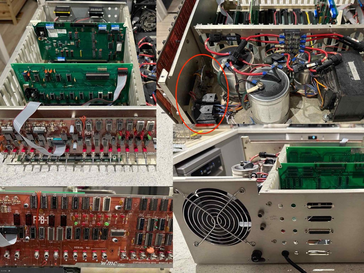
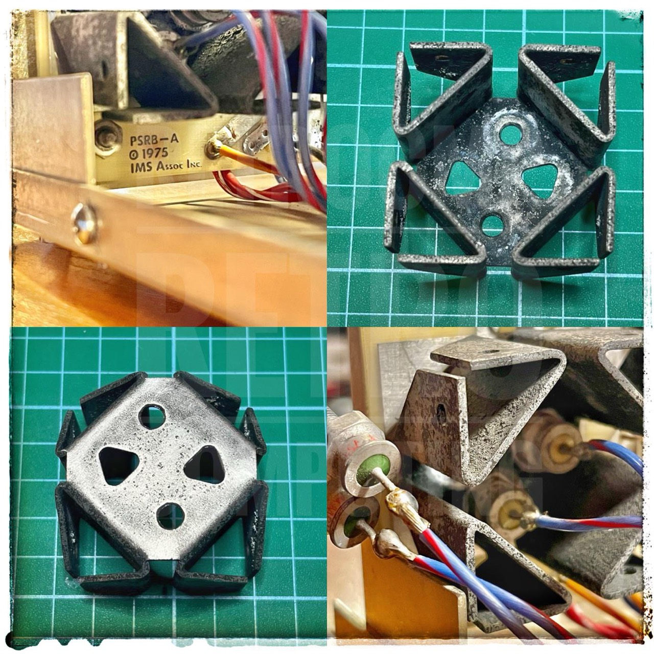
Although there is no serial number, the base plate and the power supply clearly show that this is basically a generation (0) IMSAI.
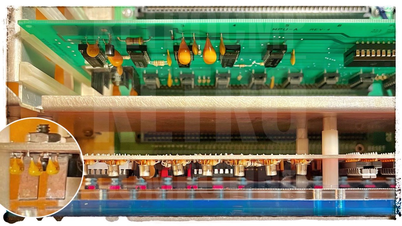
And especially an IMSAI which is to be classified in the range of serial numbers between 001-2xx and 001-9xx. This can be recognized by the additional rectifier board (PSRB-A), which is attached to the front at the rear, see next image.
I acquired this IMSAI from the estate of Ross Milbourne (as well as many other S-100 boards). There is no case top, but there is a Wameco WMC FPB1 front panel (hard to find). I don't need the case top as I want to test new S-100 boards with this IMSAI, as did my previous owner.
Case Top
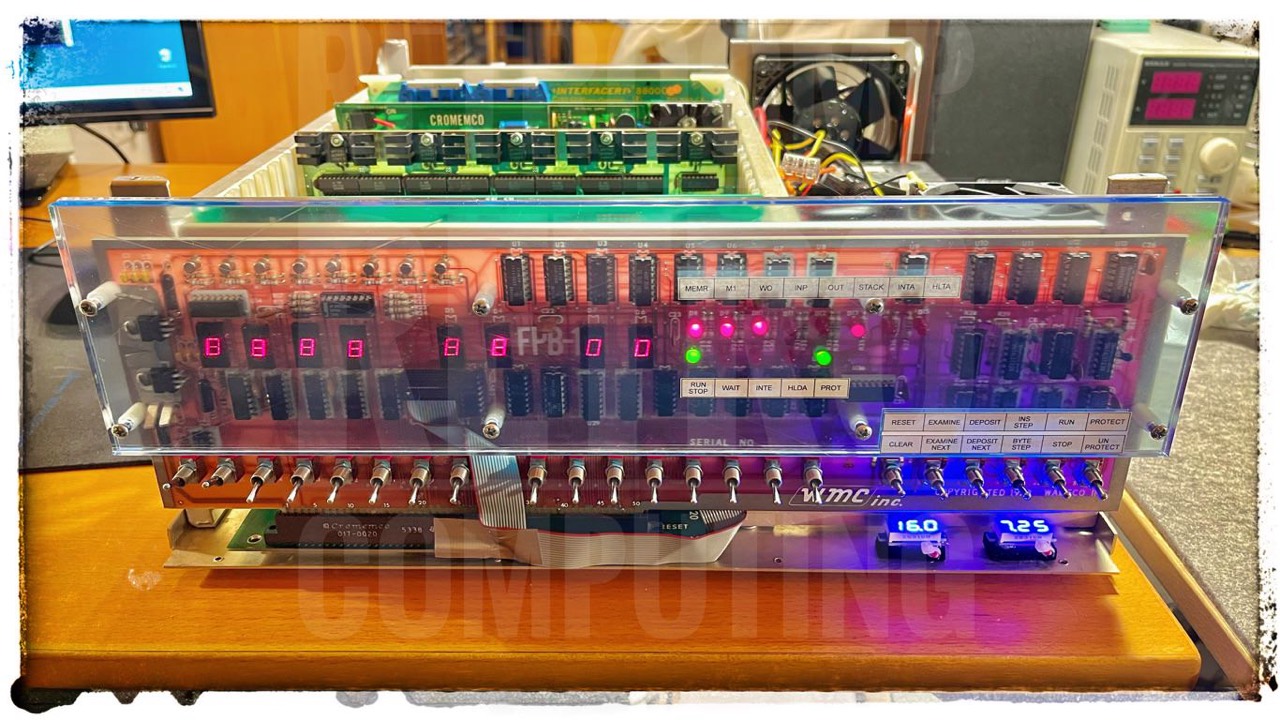
This IMSAI has no original case top, but ... here is my solution.
You can see all the details perfectly, the surface is scratch-resistant and there is no heat build-up. I have fitted a 12V fan above the rectifiers, but I only run it on 7.4 volts. [5] It works perfectly and the air flow is completely sufficient.

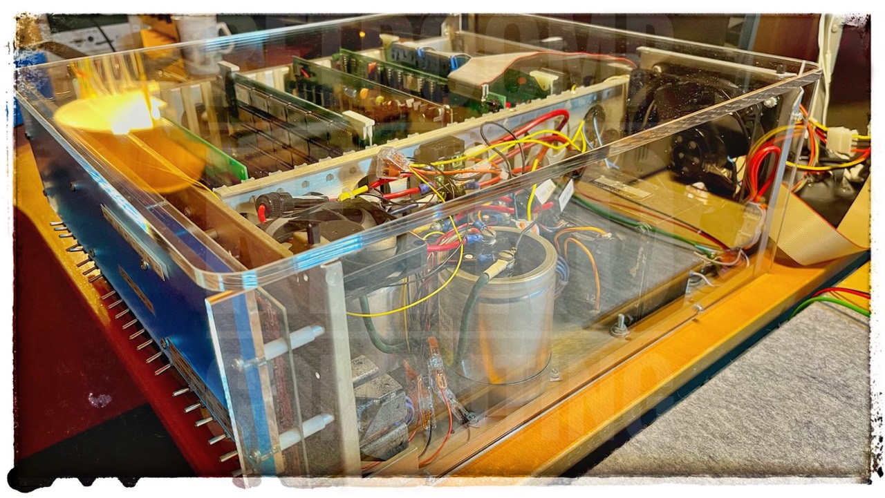
I am happy with my 2- or 3-part solution. Only the right-hand side is actually important to me, because high voltages are present here. I only use the top cover when I'm no longer working with the IMSAI; I don't want anything to fall in.
The large AC fan is therefore superfluous. However, I have also fitted a small 12V DC fan directly above the rectifier diodes (heat sink); however, it is only operated with 8V DC. More ventilation is not necessary.
Next you can see what is also possible. However, the ventilation holes are missing on the left. I would never operate an IMSAI without a fan with a closed cabinet.
I once asked for a quote (Jan 2024) for a curved plexiglass cover with additional ventilation holes. I should have paid around EUR 300 for this. Completely utopian. So I stuck with my cover.

Base and Mounting Plate
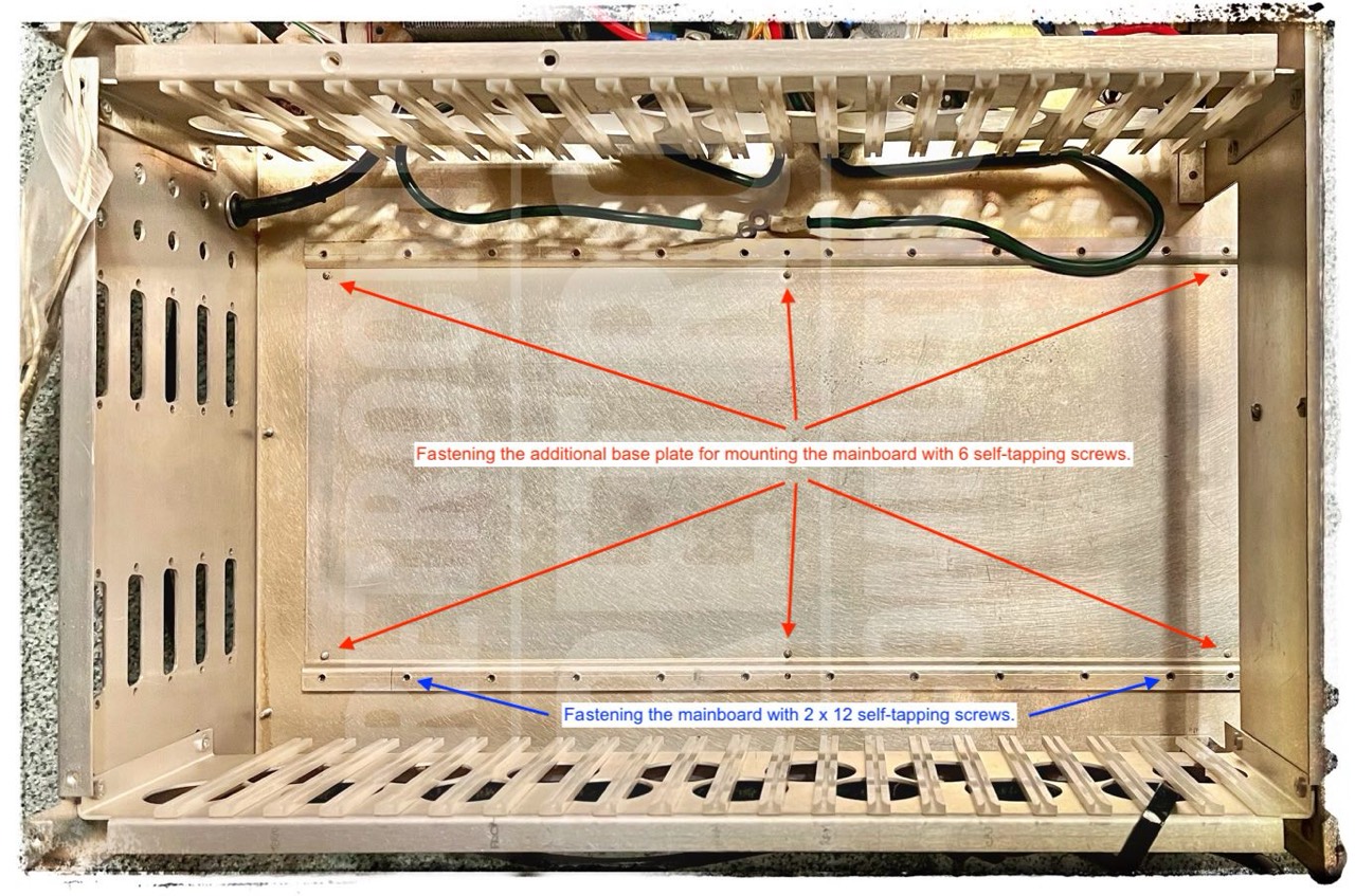
The base plate with the additional mounting plate for the mainboard belongs to the original version of the IMSAI. The additional plate is still used for stabilization, as the power supply unit is too heavy for the simple base plate.
This was only done for the first generation units -> (0).
Base Plate Revision - The base plate was originally punched in the mother board area with six clearance holes for #6 sheet metal screws. Six #6 hex head sheet metal screws (HSMS) entered from the underside and engaged the motherboard mounting plate. This arrangement provided a functional method of stiffening the base plate, which was prone to flexing from the weight of the transformer in the power supply. The motherboard mounting plate was punched with 24 holes that allowed the builder to fasten the motherboard to it with #6 HSMS. The screws went through twelve holes along each side of the motherboard, through a nylon or black fiber insulation washer, and into the mounting plate. A thick Mylar insulation sheet slipped under the assembled motherboard to help insulate the socket pins from the base plate. [2]
Front Panel
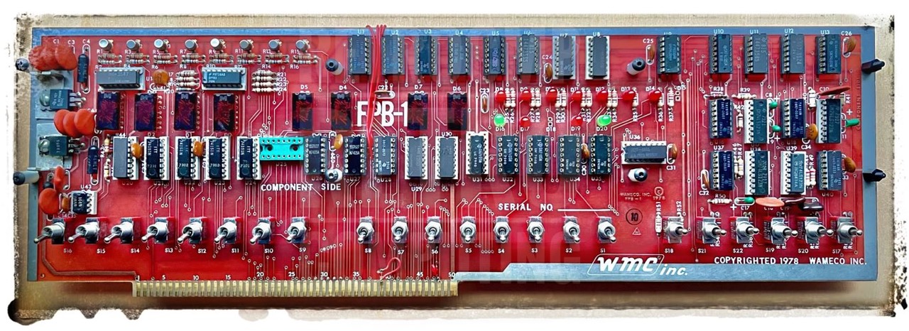
In addition to the FPB-1, there is also the FPB-1A version.
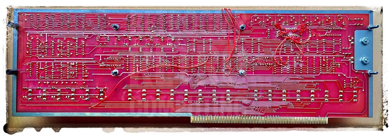
I have checked all TTLs with my Polar D320. All are ok. I still have to re-solder a torn wire on the back and then we'll see ...
Update 01/07/2024; As you would expect, the previous owner probably tinkered with this front panel a little. It does not work properly. So what to do. However, as I lack a lot of specialist knowledge for such a repair, I asked a specialist. The name Jonathan Chapman (The Glitch Works) should be familiar to everyone in the S-100 scene. So I packed the board well and sent it to the USA. It arrived safely after a long journey. After just two days, Jonathan had solved the problem and I'm looking forward to its return. It will probably take a while yet. I will report back.
The Result: "All fixed up! No dead chips, just a mix of nonworking previous repairs (what happened to this board?) and some bad original soldering on the switches. I did replace one loose switch, and installed two missing LEDs."
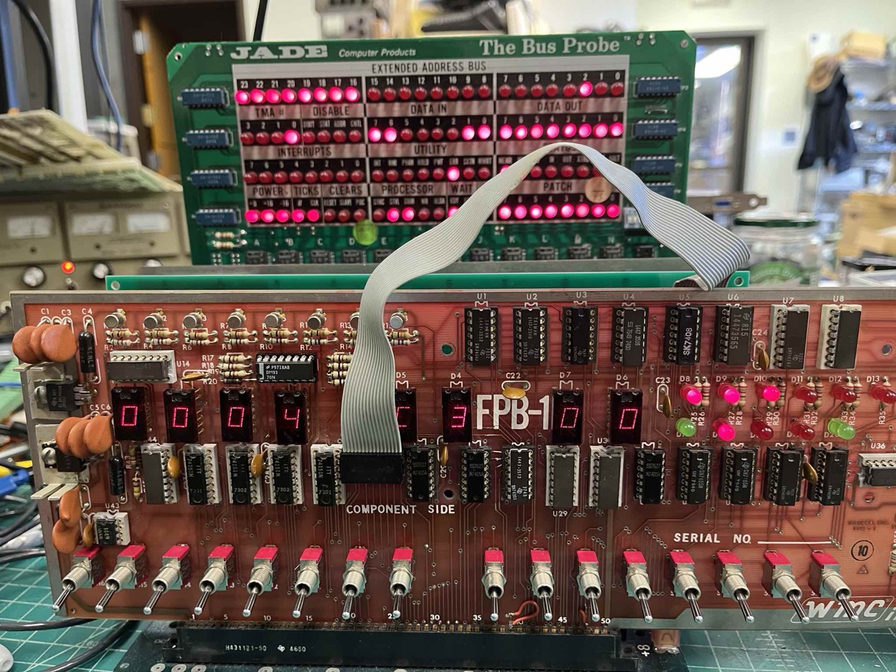
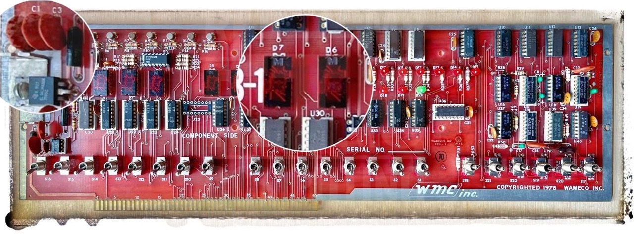
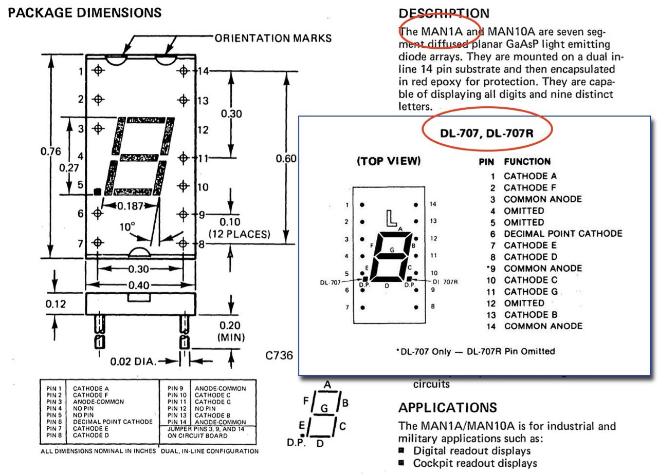
This front panel is characterized by a special feature. Instead of the usual IMSAI "bit" LED display, it has hexadecimal LED displays. My board uses Monsanto MAN1A 7-segment LEDs. In addition to the MAN1A there is also the DL-707 and the TIL312 but these looks quit different. On ebay the MAN1A is been trading for $20-30 per piece (Jan 2024). But I didn't even pay that much for the entire front panel. You have to be lucky sometimes.
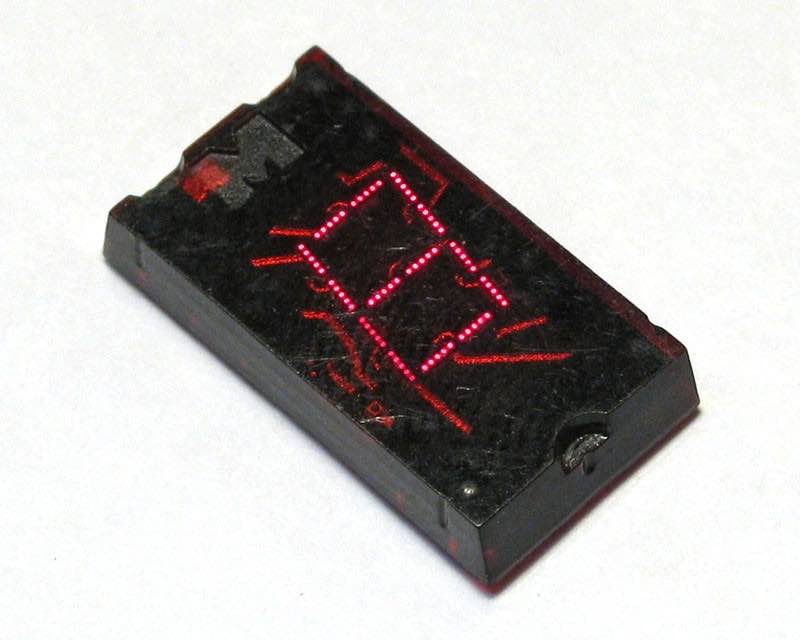
The Monsanto MAN-1 is generally considered to be the world's first production seven-segment LED display. Following the introduction of the MAN1, the now-familiar seven-segment LED rapidly took over the world, wiping out the demand for Nixie tubes, Panaplex displays, Minitrons, and nearly every other display technology in a single blow. Each segment of the MAN-1 is made up of a pair of silicon dies, which have been mounted to a printed circuit substrate and buried in clear epoxy. Each die is masked in such a way as to divide the light output into four separate dots, which is what gives the MAN1 its characteristic bitmapped appearance.
The MAN1 also includes a decimal point, which is made from what appears to be a single MV1 die. The MAN-1's first-generation diode technology results in a very dim display, but the virtual immortality of LED technology showed a potential that Nixie's and incandescent displays could not hope to compete with.
Soon after the release of the MAN-1, Monsanto introduced a modified version, the MAN-1A. The MAN-1A is identical in functionality and basic construction to a standard MAN-1, but has a dark red epoxy case which does a great deal to hide the display's ugly internal construction. [5]
Since the last owner did not use a Plexiglas shield, the large disk capacitors (50V, 0.1 uF) C1, C2, C3, ... did not play a role. However, as with the original IMSAI, I had two Plexiglas panels made and the spacers would have been extremely long (6/8" or 20 mm). I therefore replaced all the disk capacitors. Now I can use 12 mm (1/2"). And because I was already there, I also replaced both 7805 regulators as a precaution.
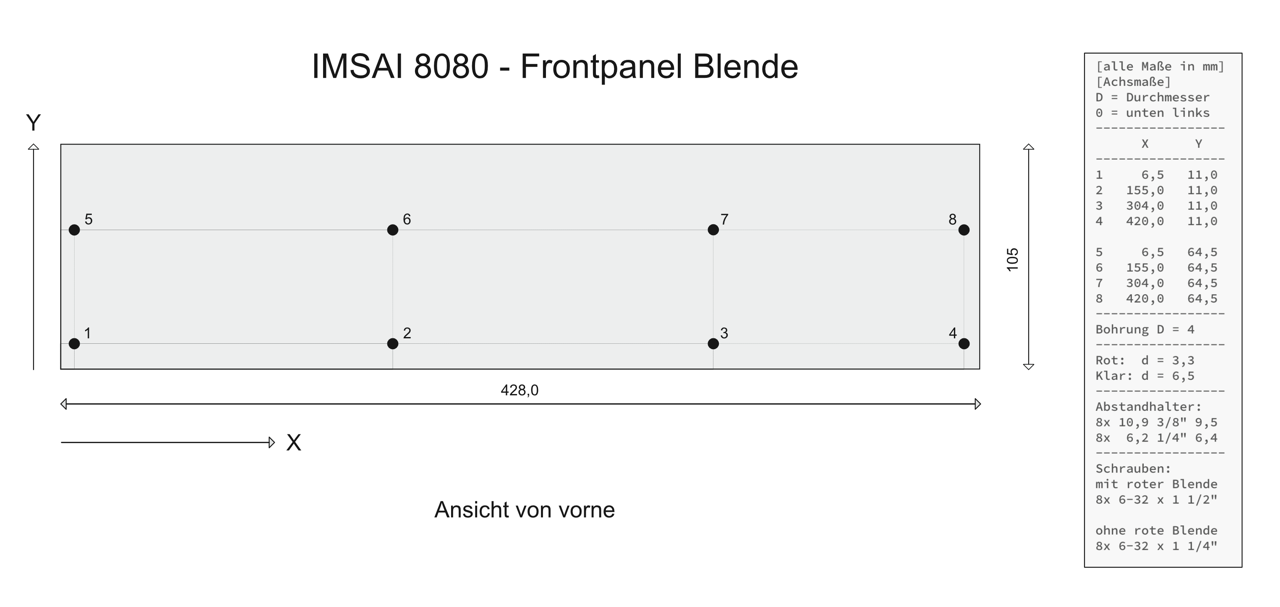
New Plexiglas shield/panel with two 1/2" spacers. Fits perfect with 1 1/2", 6/32 screws. Now I just have to place a suitable photomask between the two panels.
Back Panel
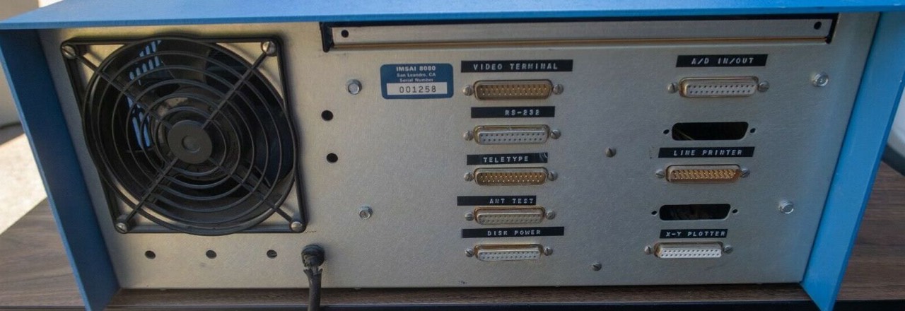
The original back panel was replaced by one of the previous owners with a panel from the series or generation (1). There are 2 x 5 vertical holes to the left of the DB-25 cutouts.
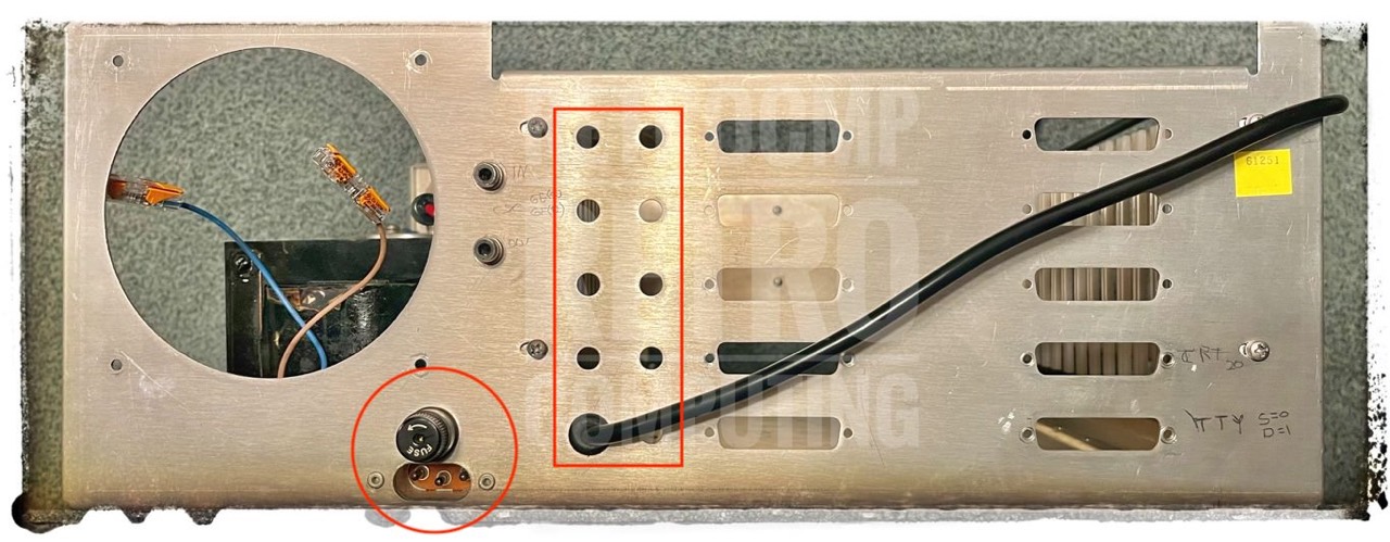
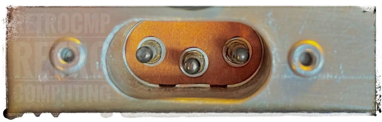
A fuse and an additional AC socket were also installed. Both modifications were carried out professionally. The socket is fastened with blind rivets.
Power Supply Unit - PSU

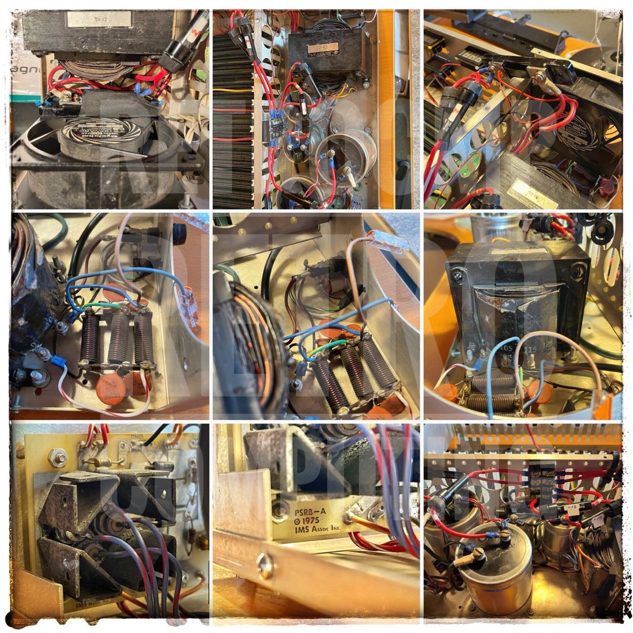
The power supply components are installed directly on the base plate.
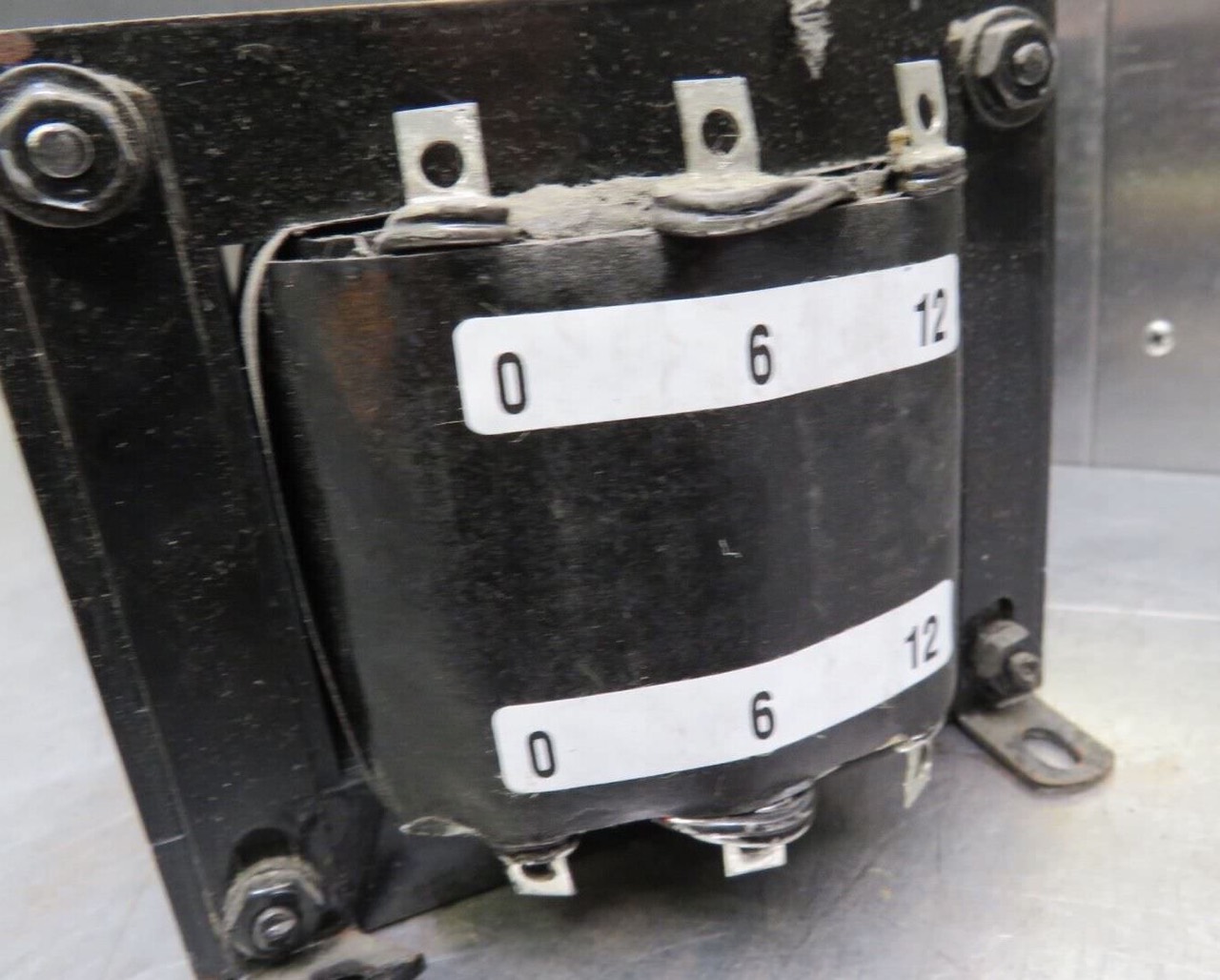
Transformer
The transformer is a Signal 24-12.
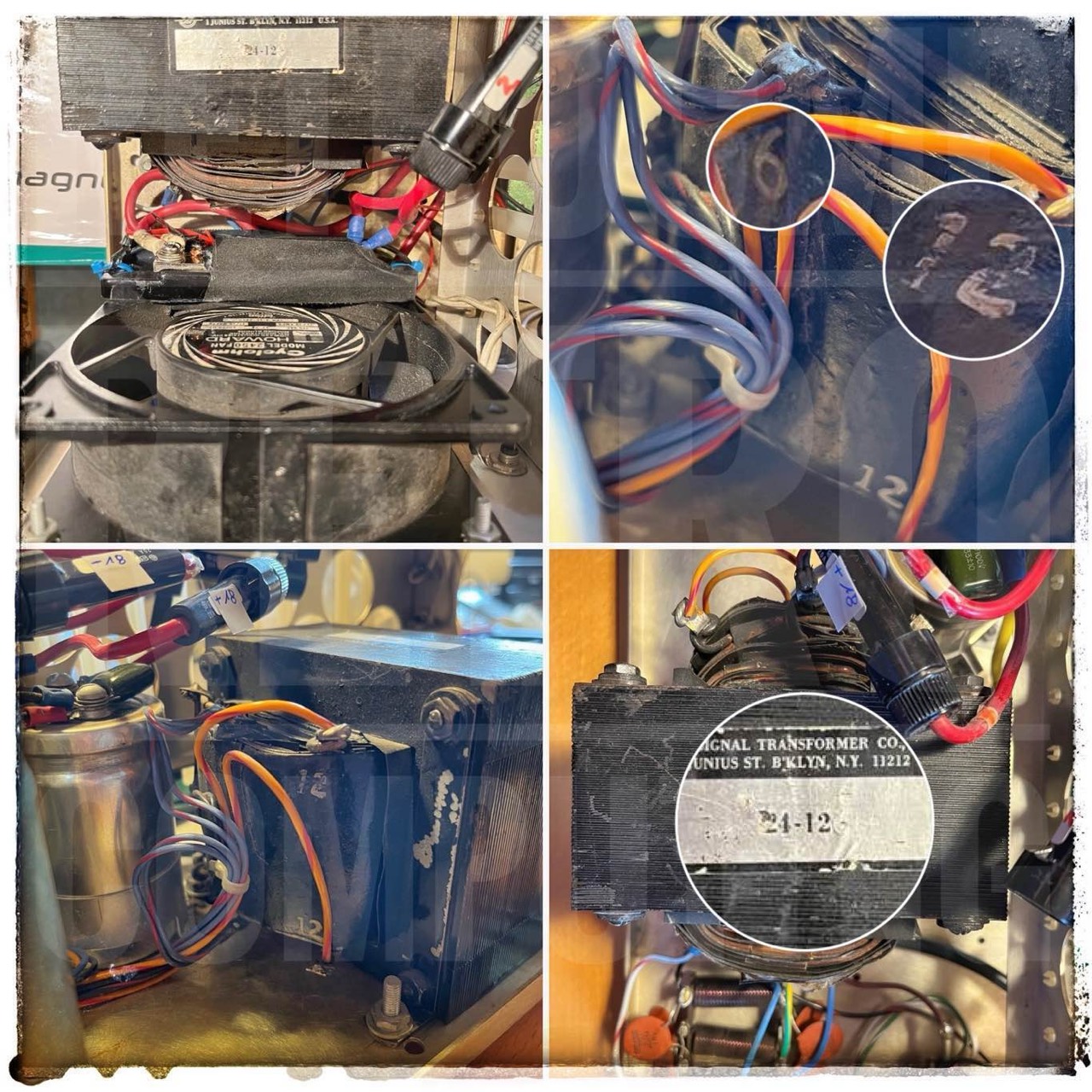
This model still seems to be on the market today. There are three taps on the (single) primary: side 105 V, 115 V and 125 V; nominal is 115 V. My transformer was conntected to the 105V tap; I changes this to 115V. The new ones can be used at 50 Hz or 60 Hz. The old ones I do not know.
The secondary side has five taps. 2x 6V, 2x 12V and a center tap. I have measured 12,5 VAC and 6,3 VAC. The following DC voltages are generated on the rectifier board from these two AC voltages: 7.4 VDC, 16.0 VDC and -16.8 VDC.
AC Filter Inductors
The presence of the three AC filter inductors is striking here. They are always present on the later PS-28 power supply units (with the additional PSU base plate) but not on the first ones without the second base plate.
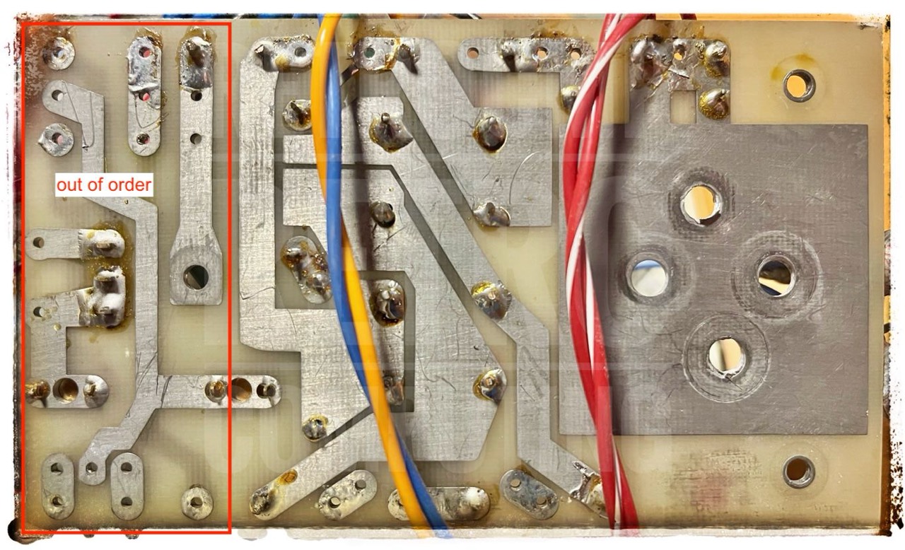
Rectifier - PSRB-A
All four rectifiers on the 8V line (MR1121 or 1N1582) have a forward voltage of 0.5 V. This value doesn't mean anything to me. However, since a NOS rectifier also has a value of 0.5 V, I assume that all four are working perfectly.
The three bleeding resistors can also be recognized. 2x (brown-black-red) = 1 kΩ and once (yellow-violet-brown) = 470 Ω.
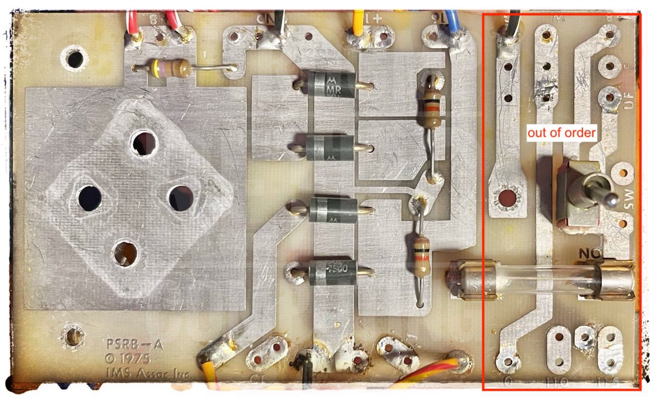
The AC line on the rectifier board is out of order; switch and fuse are not used.
Capcitors
With the exception of the C0 (CDE), the other three capacitors are identical to my other IMSAI
- C0: +8V line:
CDE Computamite: 15V, 100,000 uF (MFD)
76 x 105 mm
datecode unknown - C1: +8V line:
Temple: 15V, 95,000 uF (MFD)
75 x 103 mm
datecode 7632 - C2: +16V line:
Temple: 25V, 10,000 uF (MFD)
50 x 77 mm
datecode 7638 - C3: -16V line:
Temple: 25V, 10,000 uF (MFD)
50 x 77 mm
datecode 7638
This issue is discussed by Ross Millbourne in his quite excellent blog about the restoration of an IMSAI 8080 for the Centre For Computing History at Cambridge, UK. You must read this blog! He also describes the reforming of old and large capacitors!
Reactivating Large old Capacitors
Here are my personal steps in reforming old capacitors. I have created a separate chapter in my Northstar blog: Reforming large old capacitors.
Every day I increase the (reforming) voltage until I have reached about 80% of the maximum voltage. Then I look further.
- Day: C0 & C1 -> 3 V with 33 kΩ
- Day: C0 & C1 -> 5 & 7 V with 33 kΩ
- Day: C0 & C1 -> 9 V with 33 kΩ
After the third day, the two large capacitors hold the voltage very well. After 12 hours, there was only a voltage drop of 0.5 volts from the initially existing 7 volts. - Day: C0 & C1 -> 10 V with 33 kΩ
I always adjust the increase in voltage so that the current flow is max. 110 µA. When it has dropped to 30-40 µA, I increase the voltage again a little ... and so on. This process is so simple once you have understood the system. And the great thing is that it works.
I also removed the two smaller capacitors, reformed them and reinstalled them. However, both were in almost perfect working order.
PSU Variants
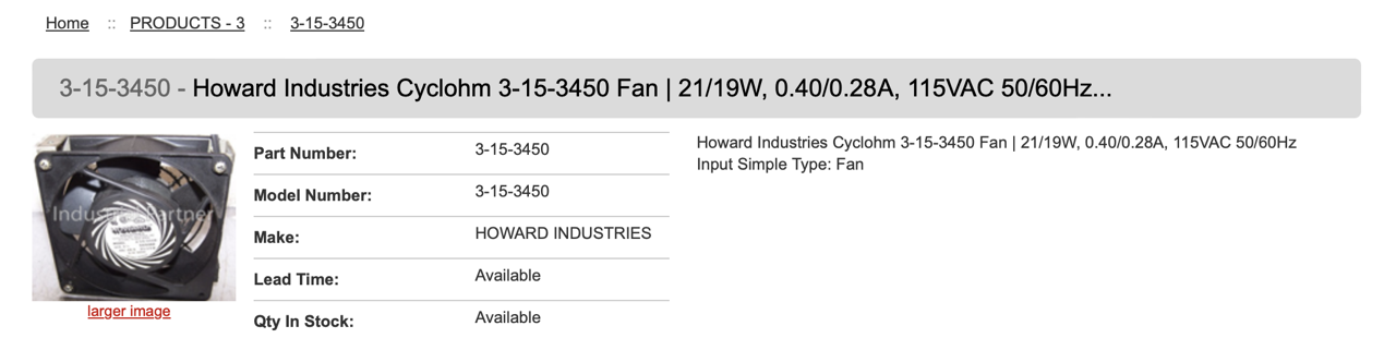
Fan
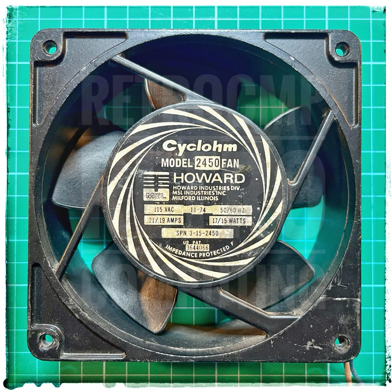
The fan runs perfectly. You can hear it at full load (115V). However, as I will only be operating the IMSAI at 105V anyway, the noise level is pleasant.
Important. The fan must be installed so that it draws in the cold air and blows it over the transformer, not the other way round!
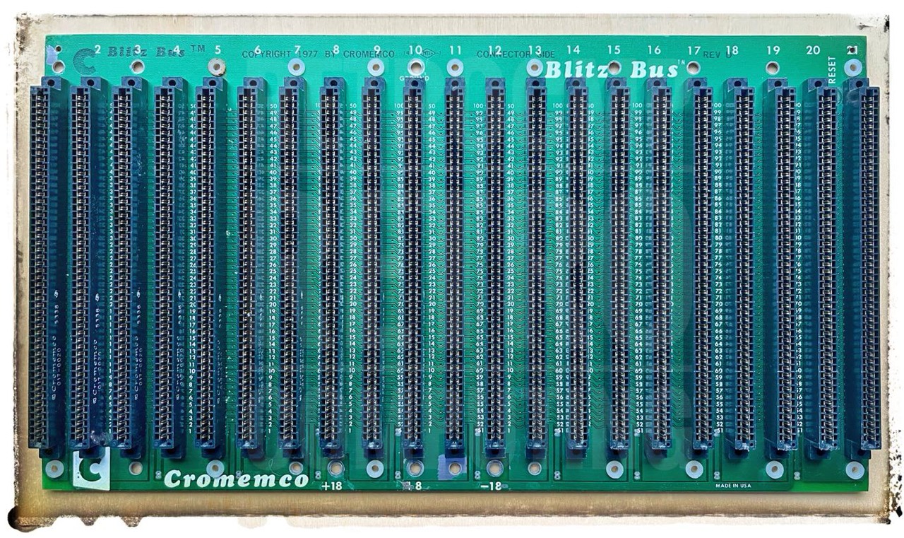
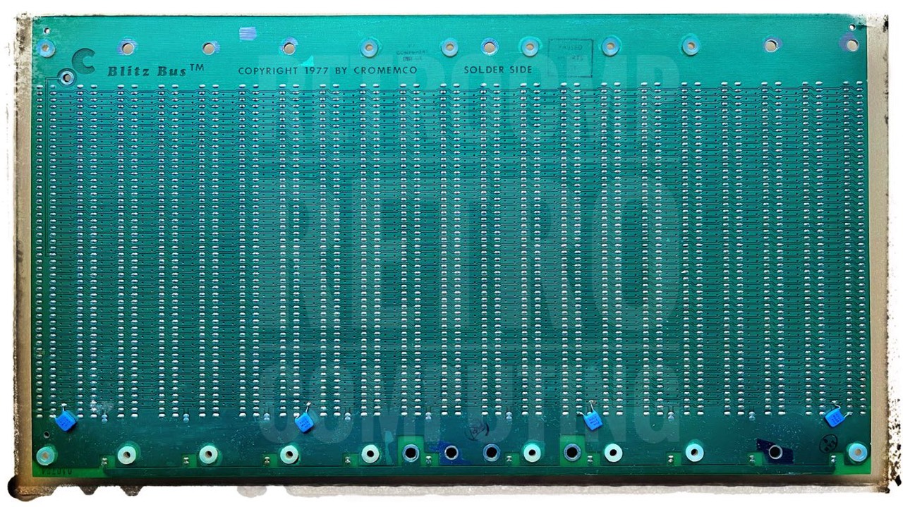
Mainboard
I have not found any further information on the Blitz Bus motherboard from Cromemco.
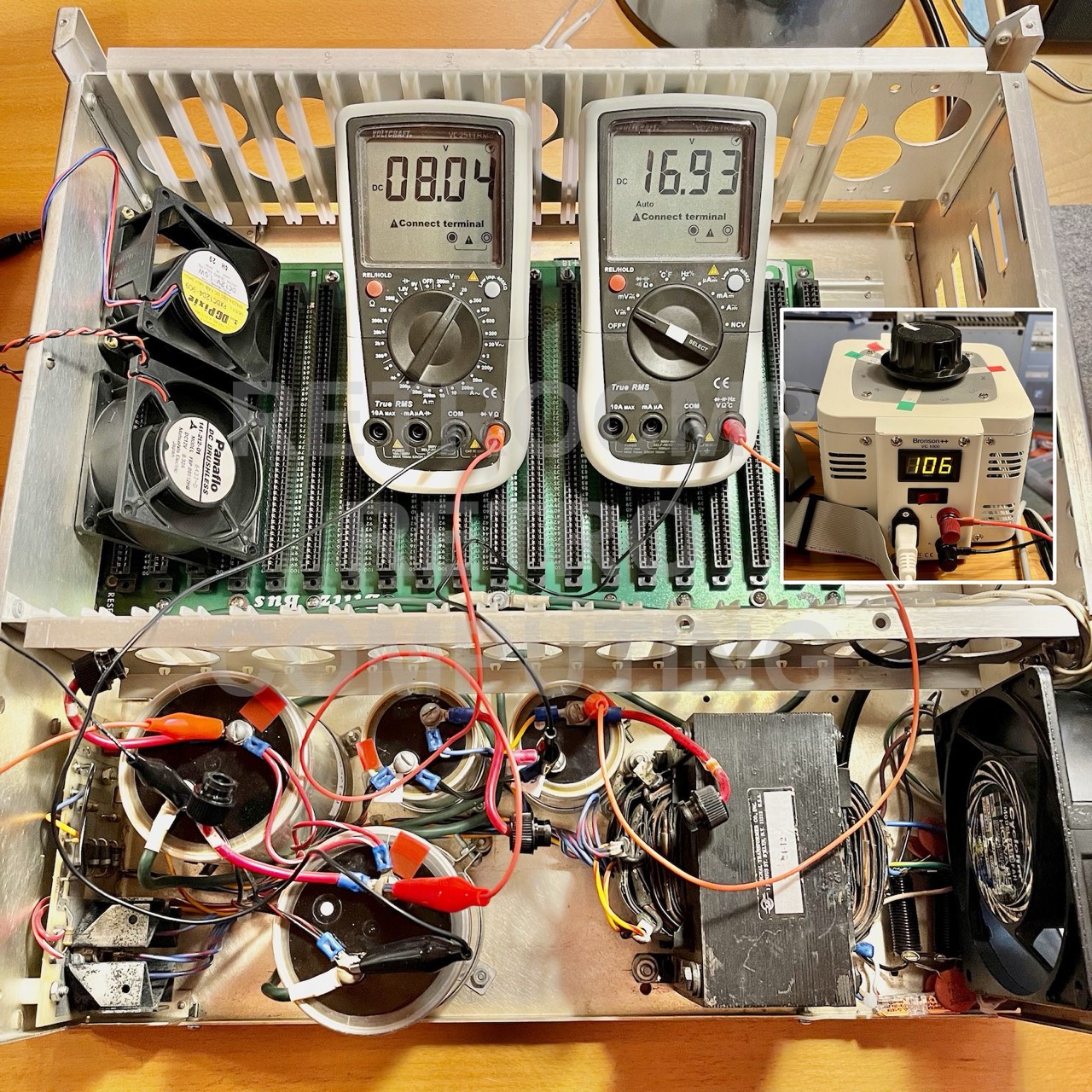
Result
The transformer is set to 105 VAC in the primary circuit. So I have also set my variable transformer to 105 VAC and the capacitors are at almost 8 VDC and ±17 VDC. What more could you want!
However, the voltages of 8 V and 17 V are only generated without load. Under normal load with non-current-hungry 5 V boards, the voltages are 7.3-7.5 and 16.5 V. Both are just sufficient.
I would say we're ready to go. Next, I'll take care of the WMC front panel. Let's see if it works as easily. Note: The trained eye has of course recognized that I have replaced the two large capacitors. I bought these two in the USA a few months ago and reformed them during this time. Now they are perfectly suitable for use. You read that right. I reformed both of them at 5-7-9 volts for months! The result is impressive.
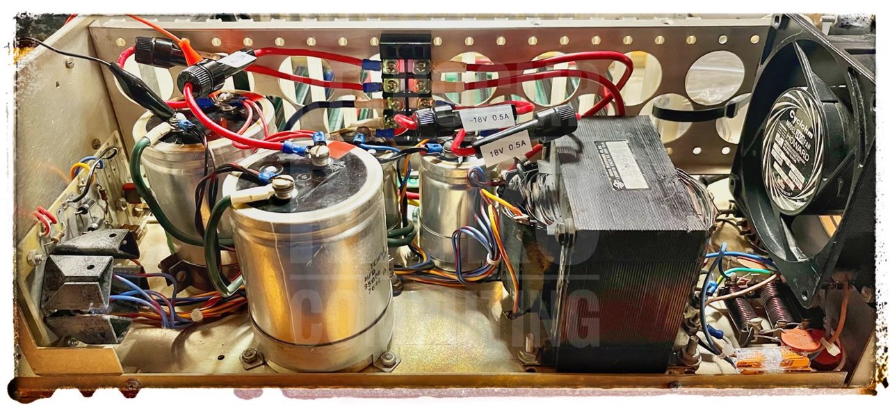
Ross Milbourne has also installed fuses. The two 8V lines are each fused with 3A and the two 16V lines are each fused with 500 mA. The 3A fuses in particular are on the safe side; 3 x 8 = 24 watts. That's not much, but it should be enough for the front panel and 3-4 boards. At worst, the fuse will blow. I will keep an eye on it and install a larger fuse (5A) if necessary.
However, the critical circuit is the -16V line. Boards that require -5V can sometimes have a short circuit (defective capacitor). I have already had to repair the -16V line on my N* Horizon motherboard twice! That makes no fun.
Update 03/26/2024: These little fuses saved the life of my mainboard at least twice! They are extremely important, especially for a test computer.

All power supply components are almost 50 years old but they work (perfectly).
Downloads
Here you will find all my gathered downloads for the IMSAI.
Information
- Here you will find all my gathered downloads for the IMSAI.
- You must read this blog: Ross Milbourne - Restoring an IMSAI 8080 for "The Centre For Computing History at Cambridge", UK, 2020
References
- (↑) ebay sales pictures
- (↑) Thomas Fischer, https://web.archive.org/web/20180709082914/http://www.imsai.net/support/first_imsai.htm
- (↑) https://www.facebook.com/groups/s100computer/permalink/6792883070833940/, Allioli Hand Made
- (↑) Approx. 7.3-7.5 V are present at the rectifier output. This is (still) sufficient as an input voltage for the 7805. According to the test conditions, the input voltage should be between 7.5 V and 20 V. I am therefore slightly below this.
- (↑) Industrial Alchemy, https://www.industrialalchemy.org/articleview.php?item=463
- (↑) https://www.elektormagazine.de/magazine/elektor-138/56976
- (↑) GI Monsanto Optoelectronic Products, 1983
- (↑) Litronix Optoelectronics Catalog, 1982
My Series About the IMSAI 8080
--> Go to Part 0: Information
--> Go to Part 1 : Restoration (1) - Restoration (2) - Restoration (3)
--> Go to Part 2 : History
--> Go to Part 3 : Front Panel
--> Go to Part 4 : Emulator
--> Go to Part 5 : PSU
--> Go to Part 6 : The High Nibble
--> Go to Part 6 : RAM (of my North Star series)
--> Go to Part 7 : S-100 (of my North Star series)
--> Go to Part 8 : Capacitors (of my North Star series)