<-- Back to Part 7: S-100
--> Go to Part 9: Virtual Horizon
WHEN HANDLING ALTERNATING CURRENT OR DIRECT CURRENT, THERE IS ALWAYS A DANGER TO YOUR PROPERTY, YOUR BODY OR YOUR LIFE.
!!! WARNING !!!
Reforming Large Old Capacitors
I am not an IT specialist or an electrician. I have only compiled the information and procedures presented below from various sources on the Internet for my personal use.
What is Capacitor Reforming?
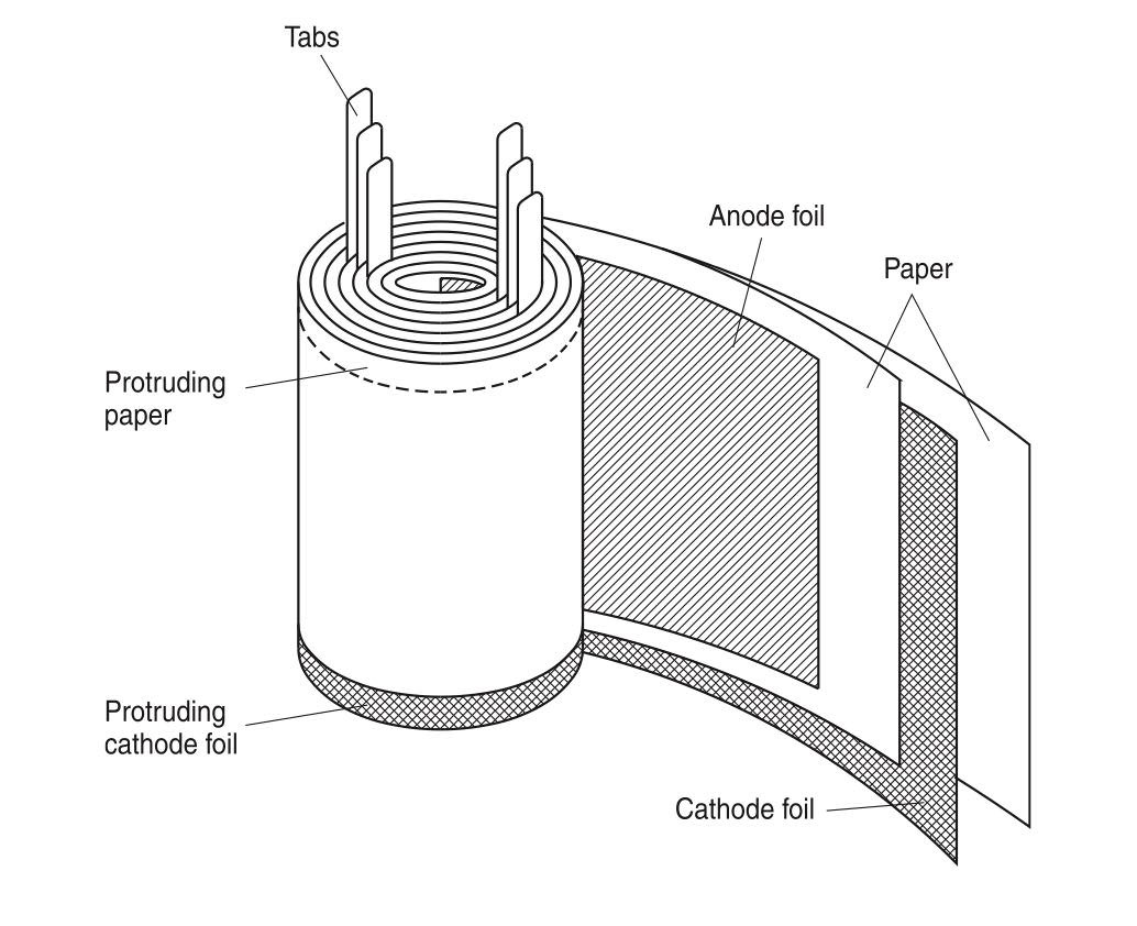
It’s helpful to understand that the electrolytic capacitor consists of two plates made of a thin aluminum alloy foil. The plates are separated by paper or an aluminum oxide layer to provide electrical isolation. The foil assembly is rolled up for placement in the familiar cylindrical shape packaging. All of the elements are bathed in a conductive electrolyte liquid.
One plate connection is designated the anode (+) while the other plate connection is marked as the cathode (-). The dielectric insulation between the plates comes from an aluminum oxide coating that forms on the anode foil plate. This coating occurs when a DC voltage is applied to the cathode plate during manufacturing. Reforming a capacitor refers to a process that restores the degraded aluminum oxide coating.
Under normal operation, the interaction between the electrolyte fluid and the electric field around the charged plate maintains the thickness of the aluminum oxide layer. Plate size determines the capacitance rating in Farads. The thickness of the oxide layer determines the voltage rating of the capacitor. Other parameters affect the temperature rating.
Why Do Capacitors Need to be Reformed?
Whether capacitors are stored as a component or installed as part of an equipment assembly, the result is the same. Electrolytic capacitors that remain unpowered for longer than 6 to 18 months can experience degradation of their aluminum oxide dielectric insulation. Power applied at the capacitor’s rated capacity can exploit any weakness in this insulation. This will allow the voltage to punch through to a short circuit condition.
The resulting short circuit of a capacitor results in physical and electrical damage to the capacitor. It also leads to catastrophic failure of the equipment. A severe failure of a capacitor can also cause collateral damage to surrounding equipment. For example, built up pressure inside a failed capacitor can cause physical damage in the surrounding area from capacitor material being expelled. Or, combustion damage to fragile circuitry and other components is possible. This type of failure can possibly pose a risk to personnel in the area in the event of a failure.
A rigorous schedule for reforming capacitors should be incorporated in your facility maintenance schedules. This will prevent damage to spares and intermittently idle plant systems. Manufacturers of drive and other power supply equipment that uses large electrolytic capacitors include capacitor reforming schedules in the applicable documentation.
What is the Procedure to Reform Capacitors?
The typical procedure consists of applying a small DC charge at a controlled current over a period of time. Slowly increasing the voltage level during the procedure allows the electric field to interact with the electrolyte.
This interaction will replenish the aluminum oxide layer on the anode plate. Once completed, the capacitor can be placed into immediate service. Refer to the equipment manufacturer’s documentation for more information or consult with your electrical equipment service provider. [2]
Here is a compilation of some other information on this topic.
General information
If you ever want to own and run one of the first old computers, then you will have to deal with the subject of reforming large old capacitors. You can't get around this topic, and that's how it was for me. In the following, I will therefore only talk about these large old capacitors, such as in the N* Horizon or IMSAI 8080. These have have rated voltages of 15 and 25 VDC. Never apply my instructions to capacitors with higher voltages.
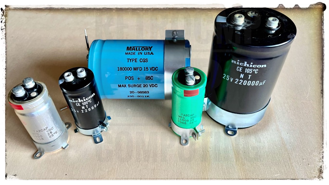
Northstar Horizon:
- Mallory CGS, 15 VDC, 180,000 μF, 8011?
- Tazcap, 25 VDC, 8.900 μF, 8008
- Tazcap, 25 VDC, 11.000 μF, 7946
- Mepco/Elektra, 25 VDC, 8.900 μF
- Mepco/Elektra, 25 VDC, 11.000 μF
- Nichicon NT, 25 VDC, 220,000 μF, 1952
- Nichicon NT, 25 VDC, 22,000 μF, 2209
IMSAI 8080:
- Temple, 15 VDC, 95,000 μF, 2x 7636 (2x 7642 spare)
- Temple, 25 VDC, 10,000 μF, 7636
The relevant source for my personal instructions is the article: Reforming Electrolytic Capacitors, Tu-Be Or Not Tu-Be Modification Manual by H.I. Eisenson, 1979. [1]
The following example refers to Mallory's large blue capacitor with 15 VDC and 180,000 MFD.
Step by Step
0 - The Good, the Bad (and the Ugly)
Before you invest any time and effort, you should verify whether it is worth reforming the capacitor at all. You can do this by measuring the ESR (Equivalent Series Resistance).
But now the question arises: how high can my ESR be? There are some tables on the internet that you should look up. But since I am not a specialist, I like to work with comparisons. This is also the case here. See next, the ESR of my new Nichicon capacitors. Other sources on the internet say that the value (for these large capacitors) should be below 1 Ω.
- Nichicon NT, 25 VDC, 220,000 μF, (1952), ESR = 0,4 Ω
- Nichicon NT, 25 VDC, 22,000 μF, (2209), ESR = 0,5 Ω
Mallory CGS, 15 VDC, 180,000 μF, (8011?), ESR = 0.46 ==> OK
1 - Patience and Time & Less is More
Even in science fiction films, the main characters are only very slowly awakened from their cryo-sleep. It takes hours if not days. If you don't have patience and time with your capacitors, then please jump straight to the bottom of this page and deal with other things.
Basically, the following applies: Low voltage (1 to 3 VDC) and little current flow (< 2 mA).
2 - Voltages
For the large Mallory I use 4 test series. Each test series is done with a slightly higher voltage. I always start with 3 VDC. The last test series ends at about 2/3 of the rated voltage (Vp) or at the operating voltage (Vop) plus 5-7%.
I do not use or test the rated voltage indicated on the capacitor. The next test series may only be started when the last one has been successful. Each test series can take hours!
Example N* Horizon, Mallory: 3, 6, 9 & 11 VDC; note: the Horizon is operated with 10 VDC but you only need 8 VDC.
3 - Current, Leakage and Resistor
As already mentioned above, the current during reforming is of decisive importance. And here it is the so-called leakage or leakage current (LC). You can find the information on the leakage in the respective data sheet of the capacitor or you have to choose it carefully, see the following figure of Integrated Publishing Inc..
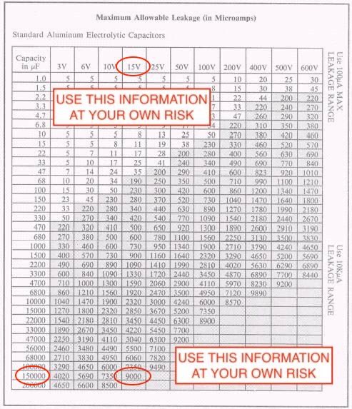
Assumption N* Horizon, Mallory, 15 VDC, 180,000 MFD: 9,000 μA or 9 mA as a rough guide, see table above.
For comparison, the maximum LC for the new Nichicon 25 VDC, 220,000 MFD is about 5,000 μA or 5 mA.
The current flow between DC source and capacitor must be limited by using a suitable resistor. According to Eisenson [1] anything from 20 kΩ to 50 kΩ will do. Other sources talk about 10 kΩ.
With my capacitors, I have always managed with a 10 kOhm (0.25 W) resistor. The actual current flow was always less than 500 μA. As a reminder, the leakage values for these large capacitors are usually between 3,000 and 9,000 uA.
In theory, a max. current of 5,000 μA can flow safely through a 10 kΩ (0,25 W) resistor. If I want to be on the safe side, then it should be a 33 kΩ resistor.
P = I² x R
I = √(P/R) = √(0.25/10,000) ≙ 5,000 μA
I = √(P/R) = √(0.25/20,000) ≙ 3,536 μA
I = √(P/R) = √(0.25/33,000) ≙ 2,752 μA
Warning: These calculations are only a rough guide for my own capacitors. For your capacitors you have to calculate yourself, you can't just take my values.
4 - Test Setup - part 1
You need ...
- an adjustable DC voltage source,
- a resistor,
- multimeter for the voltage,
- multimeter for the current.
I use a simple DC/DC converter of KEMO; it costs 11 EUR. I use an old EPSON 24 VDC (max. 1.4 A) PSU for input. The input can be adjusted to output voltages values between 3 and 15 VDC.
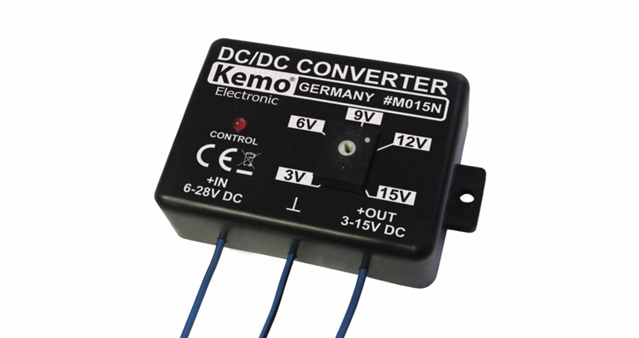
When you set the different voltages, it doesn't matter if it's 5.8 or 6.2 VDC, just make sure you do it in small steps. The roughly marked steps of 3, 6, 9, 12 and 15 VDC are sufficiently accurate for my purpose. Of course, 18 VDC or 21 VDC would also make sense, but I assume that a 25 VDC capacitor that works flawless at 15 VDC will also do so at 18 or 21 VDC. You do not need an expensive lab power supply.
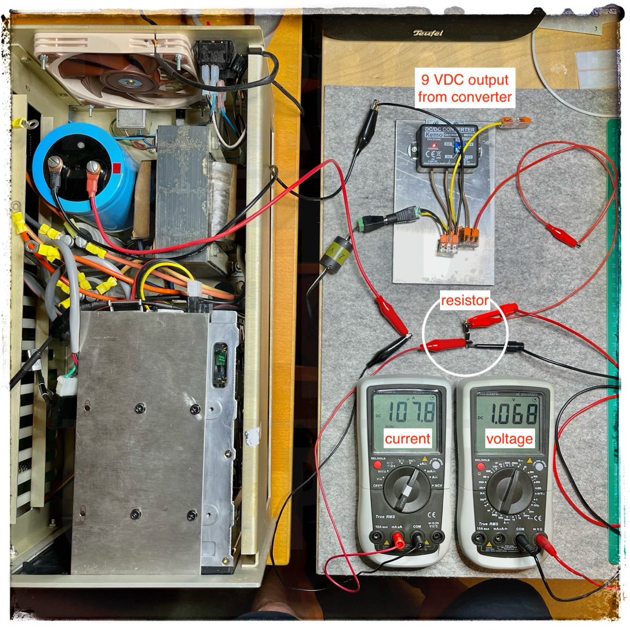
Let us get started. The negative pole of the converter is connected directly to the negative pole of the capacitor. The positive pole of the converter is first connected to the said resistor and then to the positive pole of the capacitor via the multimeter. With this multimeter you measure the actual current (μA or mA), i.e. the current flowing into the capacitor.
The current must not be greater than the previously determined maximum leakage current! You must check this value carefully at the beginning. If the current is greater than the leakage current, then stop the test immediately, check the voltage and use a higher resistor.
With the second multimeter, you measure the voltage difference before and after the resistor. In other words, the voltage loss through the resistor. The greater the voltage here, the greater the current flow.
In the next image (test setup with 9 VDC) you can see that the current flow is 107.8 μA; 9,000 μA would be the maximum allowed. The voltage at the resistor is 1.068 VDC. The DC/DC converter has an output voltage of 9 VDC. The voltage at the capacitor is therefore approx. 8 VDC.
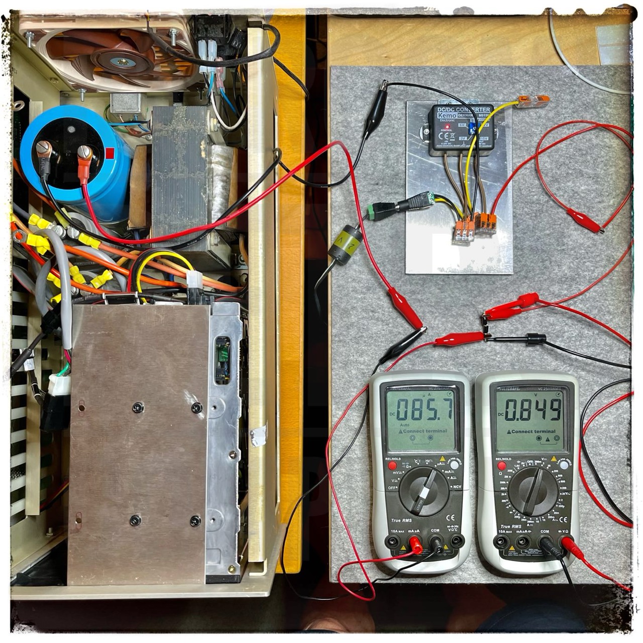
I took the next image a little 15 minutes later. What can you see? The voltage and current have decreased. And that's exactly how it has to be. If the voltage (difference) doesn't decrease, the current remains the same and the capacitor is probably defective. If this is the case, dispose of the capacitor.
According to Eisenson [1] the voltage has to drop below 10% of the applied voltage (here 9,0 VDC -> 0,9 VDC) after 1 hour. At the beginning of "my" tests, the voltage difference was sometimes 20-30 % of the applied voltage, but it always dropped (sometimes slower, sometimes faster); always below 5% and often below 2-3%.
I stop a later test series (with 6, 9 & 12 VDC) when the voltage does not longer decrease or it is below the said 3-5%. In this case with the Mallory, the final test series would now take place with 12 VDC; more than 12 VDC is not required with the N* Horizon. The aluminium oxide layer should now be reasonably restored.
But with the very first test series at 3 VDC, you have to give an old and long not used capacitor a lot of time to wake up. This is the most important test series because the voltage is the lowest. Here the dielectric insulation, the aluminium oxide layer can regenerate best. In my personal experience, these decades-old large capacitors work well again after this refreshing treatment. So, take your time!
I cannot and will not give a precise value, but if your capacitor is basically OK, then this first phase can still take hours, even a day. As I said, take your time, do not hurry!
Check if the capacitor or resistor heats up noticeably and stop the test series if necessary until you know where the problem is.
The results shown here only apply to my Mallory capacitor. The results will always be different for your capacitors. And I repeat again. If you are not sure and you don't have a clue what I am doing here, then keep your hands off it.
4 - Test Setup - part 2
Here you have to be even more careful than with the previous test setup.
You should only use this setup if you know exactly what you are doing. Why? Because you can only regulate the voltage with this primitive DC voltage generator, you have no control over the actual current flow. For this reason, you may only increase the voltage by a maximum of 0.5 volt at a time.
As soon as you increase the voltage, the current immediately increases. However, if you increase the voltage by 0.5, the current flow increases to values about 2-5 mA and then drops ... to zero (0.01-0.05 mA) within a few minutes. Of course, this depends on the capacity of the capacitor, because it has to charge up first. A 10,000 MFD capacitor is of course charged faster than a 220,000 MFD capacitor! But in the end it must drop (ideally) to nearly 0 mA.
So much for the theory, but the current flow does not drop (always) to zero. Have a look in the table above or in the manufacturer's data sheet to see how high the maximum leakage current may be. If your leakage current is below this value than everything is ok. However, if your value is (far) above this, then the capacitor seems to be defective and should no longer be used.
The basic setup is exactly the same as above, except that now I do not use a resistor to limit the current. You need ...
- an adjustable DC voltage source,
- multimeter for the voltage
- multimeter for the current
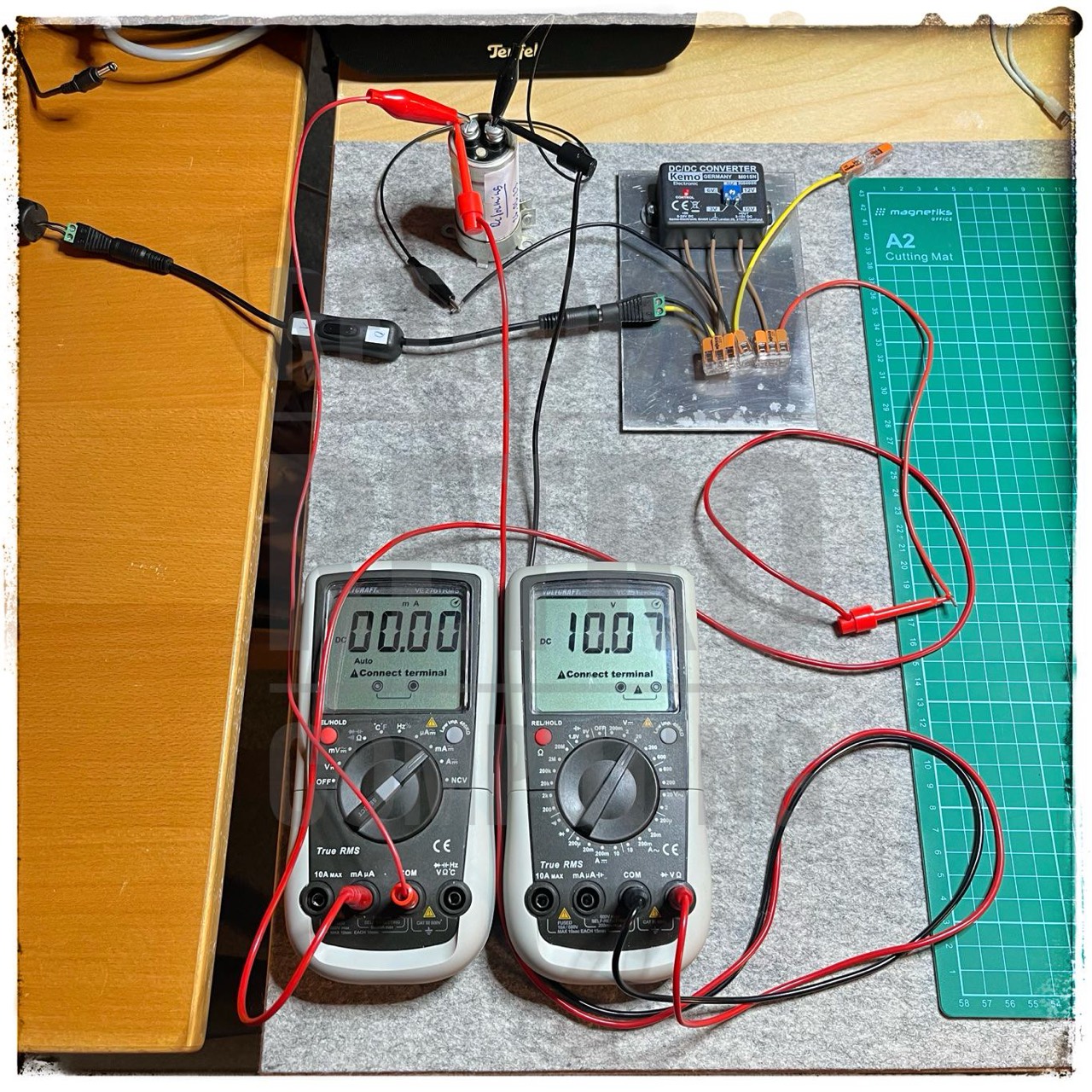
5 - Test End
At the end of the complete test series, remove the resistor and measure the real leakeage current. Then quickly release the contacts to prevent the capacitor from discharging and then measure how long the capacitor holds the last applied voltage. This should be as long as possible. That is the actual purpose of a capacitor.
Then place the charged capacitor in a quiet corner. It will discharge very slowly but will continue to reform the aluminium oxide layer.
6 - Results
So far, all my tested capacitors have been OK, even though they are almost 40 years old. In my second Horizon I use brand new capacitors from Nichicon. According to my current knowledge, a replacement would not have been necessary. The new capacitors, which have a larger capacity, work perfectly.
Temple (15 VDC, 95,000 MFD, 7642)
I have two of the large, siver capacitors of Temple as spare for my IMSAI 8080. Build date: 46/1972. I have bought them for a little money on ebay US. I have no information if they are good or how long they have been lying around. From the outside, however, they look impeccable. I only had to carefully recut the two threads (M5) a little.

Because I want to be on the safe side here, I don't use the 10 kΩ resistor but the 33 kΩ resistor. Again, I use approx. 3 VDC as the (first) input voltage. Immediately after switching on, I noticed that for several minutes there was actually 3 VDC.
With a new and good capacitor, the voltage should actually drop quickly in this test setup. But it does not here. This is a sign that the capacitor must be reformed. Even after two hours, I still measure 1.5 VDC (voltage drop) across the resistor. It is also possible that the capacitor is ruined.
I will operate it in this state for many hours. Basically, however, the capacitor remains absolutely "cold". In other words, it does not heat up a bit. Let's see what happens in the end.
With a good capacitor, the voltage (across the resistor) should have fallen below 10% of the applied voltage after one hour at the latest.
Day 1, capacitor (1): 3 VDC, 33 kΩ
- 00:00h - 2,94 V - 90,6 μA
- 01:00h - 1,90 V - 58,6 μA
- 02:00h - 1,52 V - 46,4 μA
- 03:00h - 1,42 V - 43,7 μA
- 04:00h - 1,40 V - 43,0 μA
- ...
- 08:00h - 1,40 V - 43,0 μA
Day 1, capacitor (2): 6 VDC, 10 kΩ
- 00:00h - 5,65 V - 560 μA
- 01:00h - 1,74 V - 172 μA
Next are some test series according the max. leakage current. Because in most cases nothing changed in the current flow after about 8 minutes I run my tests with this time. I have carried out several test series and often with the same VDC values. The (positiv) changes can be seen very well here. The capacitors are self healing from test to test to test!
According to the leakage chart above the maximum leakage current for the Temple should be:
- 6,500 μA at 12,5 VDC
- 6,000 μA at 10 VDC
- 4,500 μA at 6 VDC
- 3,000 μA at 3 VDC
I will test this Temple capacitors in the final test run with max. 12.5 VDC. More than that in no case. The capacitor is almost 50 years old! I have noted the max. allowable leakage current in (brackets). But these are only very rough approximations.
Leakage Current - Capacitor (1)
- Test begin: 07/17/2023, ESR = 0,43
- 0550 μA - at 3 VDC (3000 μA), day 1
- 0075 μA - at 3 VDC (3000 μA), day 2
- 0050 μA - at 3 VDC (3000 μA)
- 0022 μA - at 3 VDC (3000 μA)
- 0001 μA - at 3 VDC (3000 μA)
- 1080 μA - at 6 VDC (4500 μA)
- 0380 μA - at 6 VDC (4500 μA)
- 0140 μA - at 6 VDC (4500 μA) - 07/21/2023
- 0062 μA - at 6 VDC (4500 μA) - even better
- 0034 μA - at 6 VDC (4500 μA) - and better
- 2600 μA - at 7 VDC (5000 μA)
- 1840 μA - at 7 VDC (5000 μA)
- 0370 μA - at 7 VDC (5000 μA) - 07/21/2023
- 1070 μA - at 8 VDC (5400 μA) - 07/21/2023
- 0764 μA - at 8 VDC (5400 μA) - even better
- 0950 μA - at 9 VDC (5800 μA)
- 0230 μA - at 9 VDC (5800 μA)
- xxxx μA - at 11 VDC (6000 μA)
- Test end: 07/__/2023
Update 07/20/2023: To date, I have run dozens of test series with both capacitors. Basically, I can say that capacitor No. 2 has endured the decades of storage better because the current flow tends faster to zero.
Under no circumstances should this capacitor (1) be used at the rated value of 15 VDC. However, as there is only a maximum of 9 volts on the 5 volt line in the IMSAI, this capacitor should still be usable.
Update 07/21/2023: I connected the capacitor (1) to a normal 5 VDC PSU overnight. A subsequent test at 6 VDC shows another drop in the leakage current from 380 to 140 mA. Very good! I think if I reform this capacitor for another 3-4 days at low voltage, it should work fine again. This example shows quite well that this process can actually take a whole week or even more.
Leakage Current - Capacitor (2)
In the test series with the same voltage, you can see very clearly how the remaining leakage current (measured after 8 minutes) becomes less and less.
- Test begin: 07/17/2023, ESR 0,37
- 0015 μA - at 3 VDC (3000 μA)
- 0006 μA - at 3 VDC (3000 μA)
- 2350 μA - at 6 VDC (4500 μA)
- 0970 μA - at 6 VDC (4500 μA)
- 0090 μA - at 6 VDC (4500 μA)
- 2750 μA - at 9 VDC (5800 μA)
- 1420 μA - at 9 VDC (5800 μA)
- 4250 μA - at 12.5 VDC (6500 μA) - test end at 12.5 VDC
- 2160 μA - at 12.5 VDC (6500 μA)
- 0450 μA - at 12.5 VDC (6500 μA) - very good!
- Test end: 07/21/2023
Mallory (15 VDC, 180,000 MFD)
For my second Mallory a maximum leakage current of 60 μA (at 12.5 VDC) was measured after four test series. Allowable would be about 9,000 μA.
After 8 hrs, the voltage has dropped to 11.0 VDC; after 13 hrs to 10.6 VDC.
Nichicon (25 VDC, 220,000 MFD)
This is a replacement for the blue Mallory in my Northstar Horizon. Assuming that the capacitor should be rated for twice the operating voltage (Vop), 25 VDC (rated voltage, Vp) is not too much because the Vop on the Horizon's 8 volt line is actually up to 11 VDC.
I loaded this capacitor to the maximum voltage because it is almost new. However, I do not do this with the old ones.
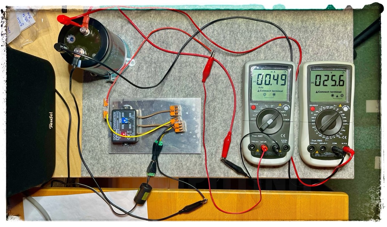
5,000 μA are allowed - very good
Voltage drop:
- 00:00 - 25,2 VDC
- 00:30 - 24,7 VDC
- 04:00 - 23,7 VDC
Mepco/Electra (25 VDC, 11,000 MFD)
A maximum leakage current of 70.0 μA (at 15 VDC) was measured after five test series. Allowable would be about 3,000 μA.
Tazcap (25 VDC, 8,900 MFD)
A maximum leakage current of 6.5 μA (at 15 VDC) was measured after three test series. Allowable would be about 3,000 μA. ESR = 0.5 Ω.
Tazcap (25 VDC, 11,000 MFD)
A maximum leakage current of 3.5 μA (at 15 VDC) was measured after three test series. Allowable would be about 3,000 μA. ESR = 0.5 Ω.
Summary
Basically, it can be said that reforming large capacitors works quite easily and leads to success if the capacitor is basically in order. First do the ESR test and if the value is about 0.5 Ω, then it should actually work. At least this was the case with me.
If you store these large capacitors at home, then you should carry out a refreshment process every year at least; this does not take so long because the aluminium oxide layer is usually still in order.
WHEN HANDLING ALTERNATING CURRENT OR DIRECT CURRENT, THERE IS ALWAYS A DANGER TO YOUR PROPERTY, YOUR BODY OR YOUR LIFE.
!!! WARNING !!!
External Links
- Integrated Publishing Inc. is one of the webs largest free online educational resources. You will find lots of technical information here but the online ads are HORRIBLE.
- There is a very informative video on this topic on YouTube by The Byte Attic. The test setup is a little different. Here, however, no resistor is used but a laboratory PSU with current limiter.
Downloads
Here you will find all my gathered downloads for the North Star Horizon.
Information
Here you will find all my gathered downloads for the North Star Horizon.
References
- (↑) Reforming Electrolytic Capacitors, Tu-Be Or Not Tu-Be Modification Manual by H.I. Eisenson, 1979
- (↑) TDK, Aluminum Electrolytic Capacitors, General Technical Information, 08/2022
- (↑) https://www.quadplus.com/capacitor-reforming
- (↑) Integrated Publishing > Construction > Navy_Construction > Navy Construction Manuals > 14026 CONSTRUCTION ELECTRICIAN BASIC: http://www.tpub.com/celec/54.htm
My Series About the North Star Horizon
--> Go to Part 0: Information
--> Go to Part 1 : Restoration & (my) S-100 Boards
--> Go to Part 2 : Hard-Sectored Disks
--> Go to Part 3 : File and Image Transfer
--> Go to Part 4 : PROM Modification
--> Go to Part 5 : History
--> Go to Part 6 : RAM
--> Go to Part 7 : S-100 Bus
--> Go to Part 8 : Capacitors
--> Go to Part 9 : Virtual Horizon
--> Go to Part 10 : S-100 Boards