<-- Back to Part 9: Virtual Horizon
--> Go to Part 10: S-100 Boards
S-100 Boards
- CPU
- RAM
- FDC
- HDC
- FPB
- FPB-A (no content)
CPU
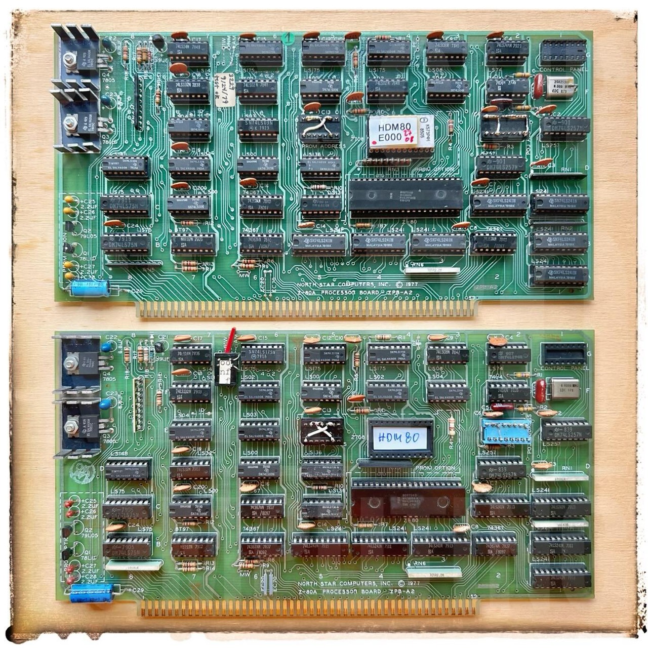
ZPB-A2 - Z80 Processor Board
Without PROM option. But I will build this later on advice by Mike Douglas. The PROM on the CPU was typically placed at E000 and the micro disk controller occupies E800-EBFF. For this reason, the North Star also has a maximum of 56K RAM (0000-DFFF). The last 8K cannot be used as RAM. Unless you can still enable the memory in smaller blocks like on the HRAM-64.
First I tested all 74*** ICs: all OK. The oldest is a 74LS02N from 7712.

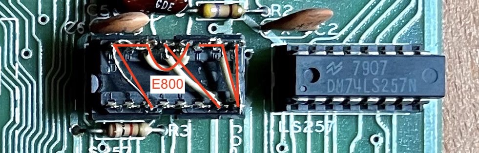
The floppy disk controller is located at address E800 by default.
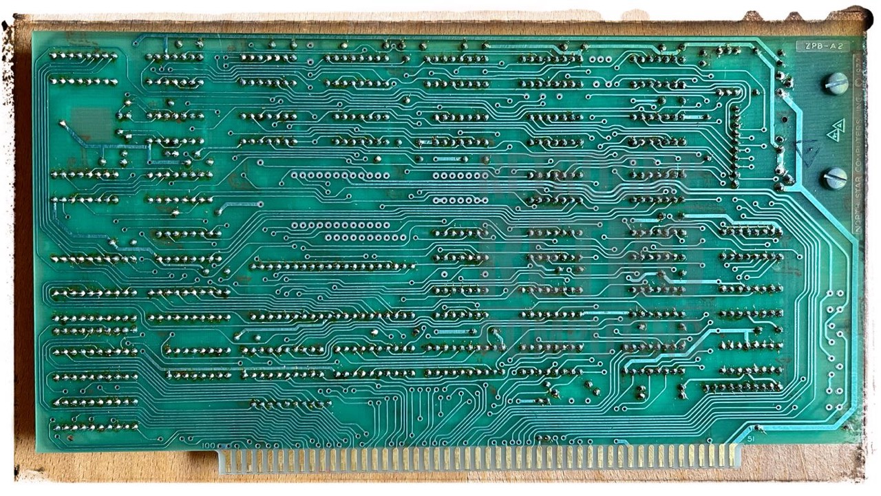
Next you can see the minimum version of the ZPB-A2 board. No PROM option, no CONTROL PANEL option and no IC sockets. I have tested the lines of the three missing 74LS241 for continuity with the multimeter. And this is what came out.

Since Sep 2023 I have three ZPB-A2 CPU boards; two with PROM option and one with none.
PROM Option
Detailed information about the two possible PROM options (original & Mike Douglas) you will find here.
RAM
N* has released a total of three of its own RAM boards:
- RAM-16-A (static)
- RAM-32-A (static) - this board can be upgraded to 64K
- HRAM-64 (dynamic)
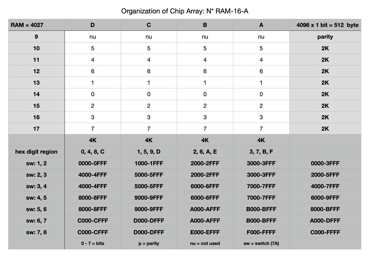
RAM-16-A - Dynamic RAM - 16K
This board is equipped with 4x8 ITT4027 3D (4,096 x 1 bit, 16 pin, date code 7846).
On the DIP header 7D below 1-2-3 and 6-7 are connected, here they soldered. This is the default setting on the N* Horizon when bank switching is not used.


The disadvantage of this memory card is that the IC RAMs of the type 4027 are hard to get and if they are, they cost a lot of money. A unit price of $4 or EUR 5 is not uncommon!
RAM-32-A - Static RAM - upgraded to 64K
R&B Computer Systems seems to have been a larger company; it is mentioned, for example, in InfoWorld magazine, Dec. 31, 1980. I have removed the label from the RAM card.
The modification from 32K to 64K was a normal procedure at that time to upgrade an existing RAM card with little effort and cost and is described in detail by Steve Leibson in The Compass Newsletter, Vol 2, No 4, page 6. [12]
The disadvantage of the 32K RAM board was already at that time that the used 8K ICs were hard to get in case of failure and the just upcoming 16K ICs became cheaper. According to the manual, six different ICs could be used in the RAM-32-A, but they were not compatible with each other. All these reasons spoke for an upgrade to 64K already at that time.
Do not be confused by the DIP header 7D below. I have only 16p and no 14p headers. 1-2-3 and 6-7 are connected; 8 is a dead end.
Unfortunately all TTL IC's on the left side are without sockets. Errors can be found very difficult if something should be defective there.
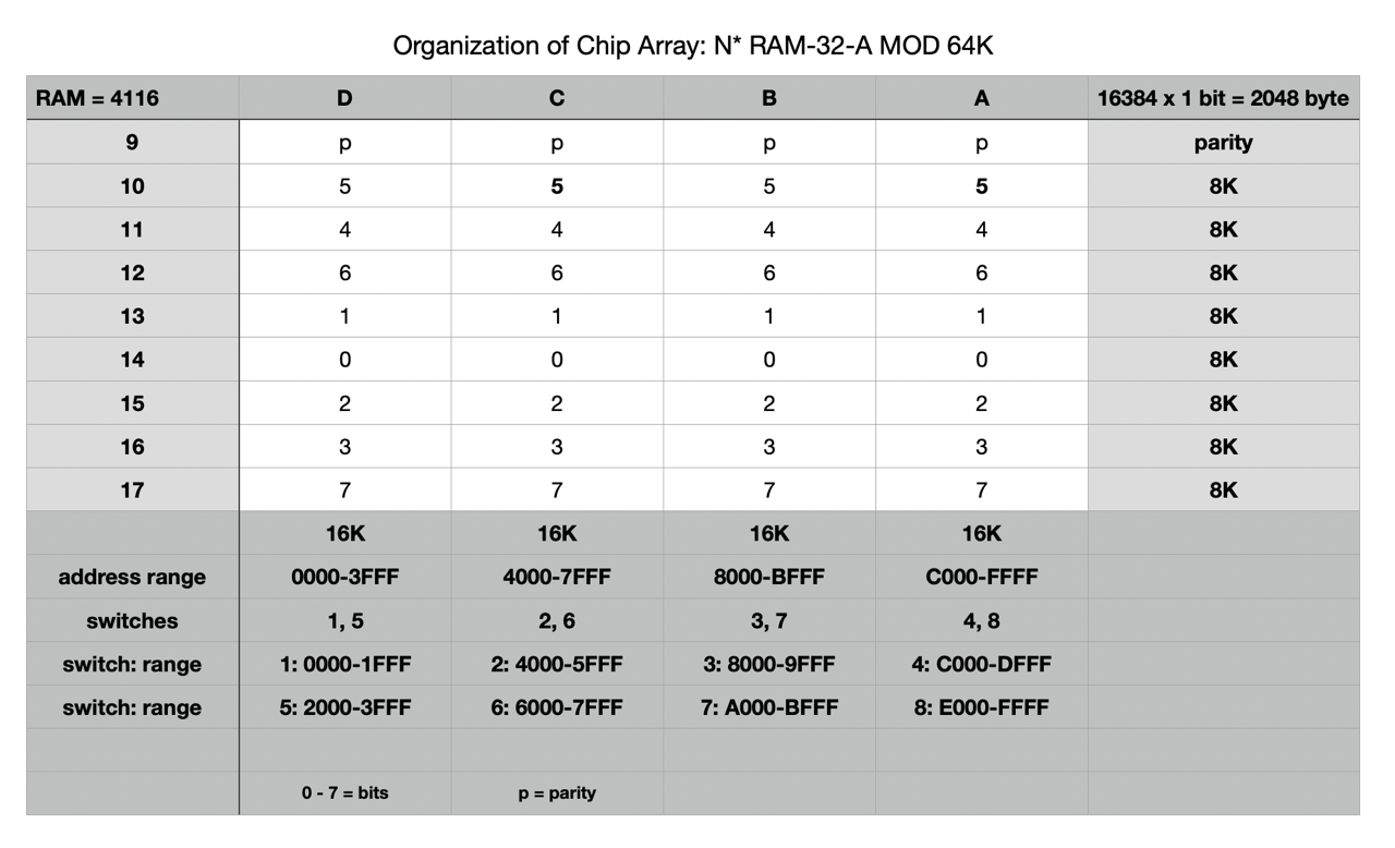
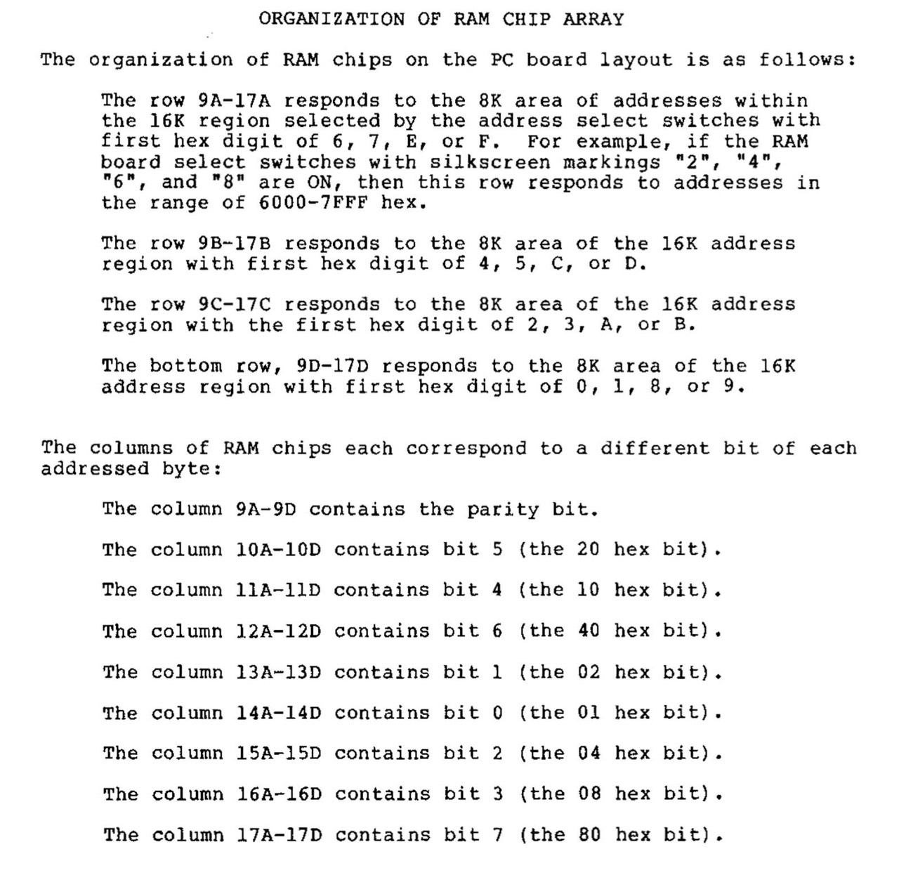
This board is equipped with 4 x (8+1) NEC upd416C (16,384 x 1 bit).

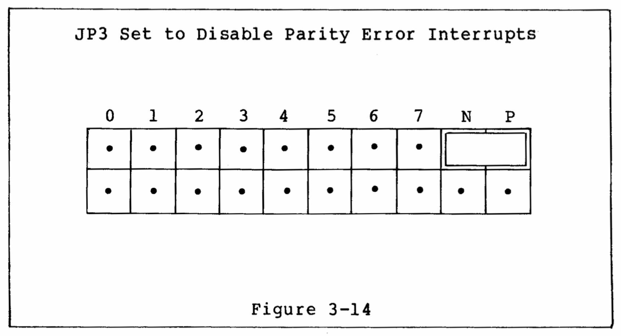
The first left column (9A-9D) contains the parity bit. The red LED (upper left) is for parity errors.

The IC's are uPD416C-1, 16,384 x 1 bit
-----------------------------------------
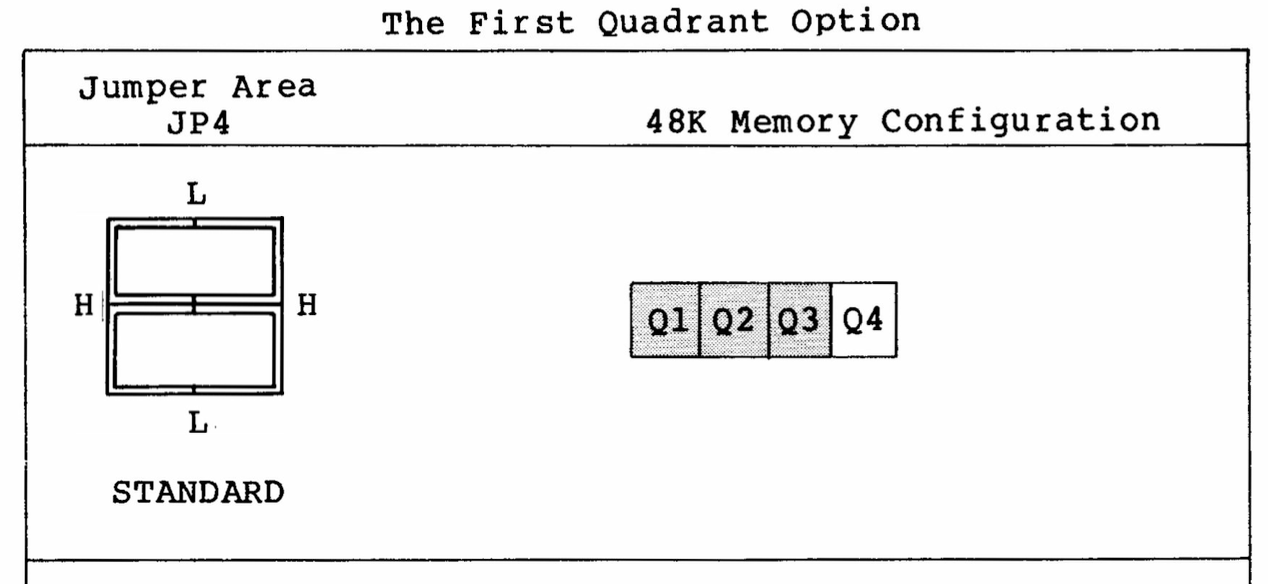
DIP switch settings: 7 x 8K = 56K
-----------------------------------------
1 ON 8K 0000 - 1FFF
2 ON 8K 4000 - 5FFF
3 ON 8K 8000 - 9FFF
4 ON 8K C000 - DFFF
5 ON 8K 2000 - 3FFF
6 ON 8K 6000 - 7FFF
7 ON 8K A000 - BFFF
8 OFF 0K E000 - FFFF
-----------------------------------------
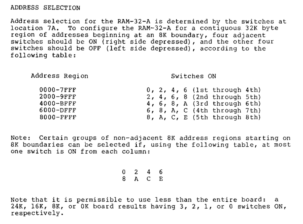
Order: 1 - 5 - 2 - 6 - 3 - 7 - 4 - 8
This order is also found in the original
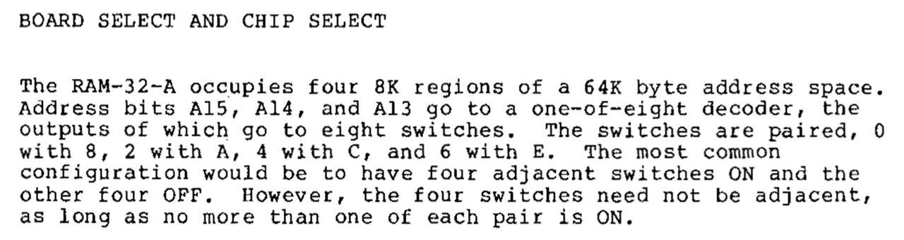
BOARD AND CHIP SELECT. Here there are the
pairings 0-8, 2-A, 4-C and 6-E. Here only
one assignment could be selected from each
pairing, see below.
-----------------------------------------
-----------------------------------------
Memory test with my PROM monitor
-----------------------------------------
1   00 - 04K    0000 - 0FFF     OK
    04 - 08K    1000 - 1FFF     OK

2   16 - 20K    4000 - 4FFF     OK
    20 - 24K    5000 - 5FFF     OK

3   32 - 36K    8000 - 8FFF     OK
    36 - 40K    9000 - 9FFF     OK

4   48 - 52K    C000 - CFFF     OK
    52 - 56K    D000 - DFFF     OK

5   08 - 12K    2000 - 2FFF     OK
    12 - 16K    3000 - 3FFF     OK

6   24 - 28K    6000 - 6FFF     OK
    28 - 32K    7000 - 7FFF     OK

7   40 - 44K    A000 - AFFF     OK
    44 - 48K    B000 - BFFF     OK, S

8   56 - 60K    E000 - EFFF     PROM, FDC
    60 - 64K    F000 - FFFF     na, FF
-----------------------------------------
Order: 1 - 5 - 2 - 6 - 3 - 7 - 4 - 8

na  not available
FF  return from PROM memory test
E   contains PROM and FDC ROM
S   stack for the PROM, BF00-BFFF
-----------------------------------------
(but with 48K CP/M)
A Faulty DIP Switch
I also had the DIP switch problem described by Mike Douglas with this RAM card. A memory area selected by DIP switch but was not present at first.
Also, DIP switches are notorious for failing as they age. The failure mode is high impedance when the switch is closed. This typically makes what should look like a zero look like a one instead. In your case, one or more of the banks on the 16K board could then be overlapping the FDC. You can easily check for this by measuring across each switch with a meter. Flipping the problem switch(es) numerous times and optionally flushing with contact cleaner can make the switch work well enough to temporarily solve the problem. [13]
North Star HRAM-64 - Dynamic RAM - 64 KByte
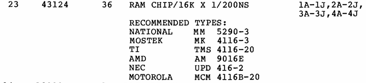
This board is equipped with 4 x (8+1) AM9016EPC (16,384 x 1 bit, 200ns). A very big disadvantage of this board: all ICs (RAM, TTL) are soldered, not good at all!
Rasmussen memory test, 04/10/2023: 10 cycles, everything is OK.

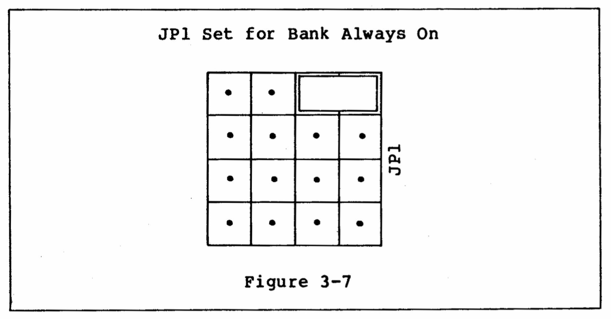
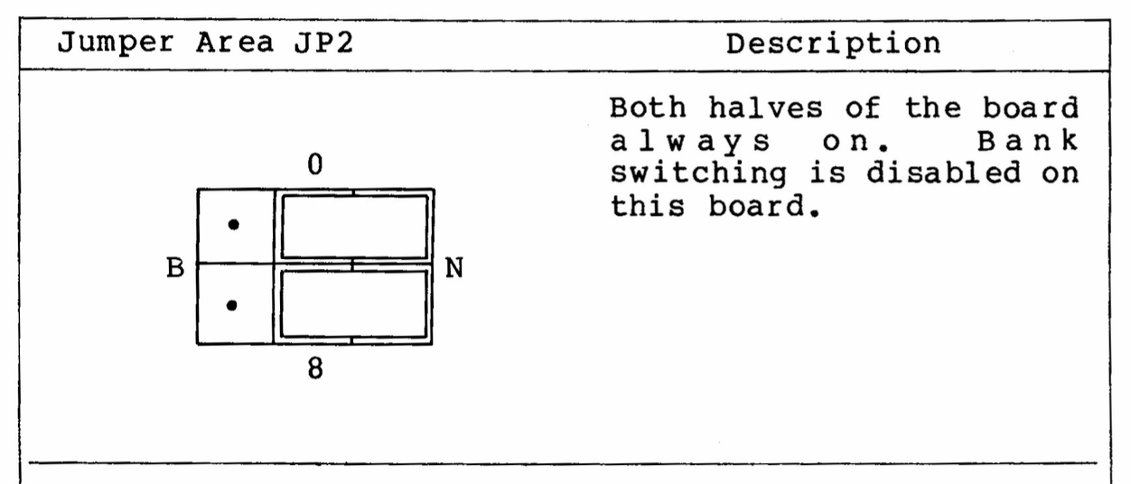
The jumper and switch settings are very easy, see below. S1: block E000-FFFF is disabled. S2: all OFF.

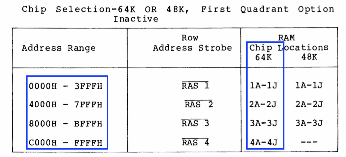
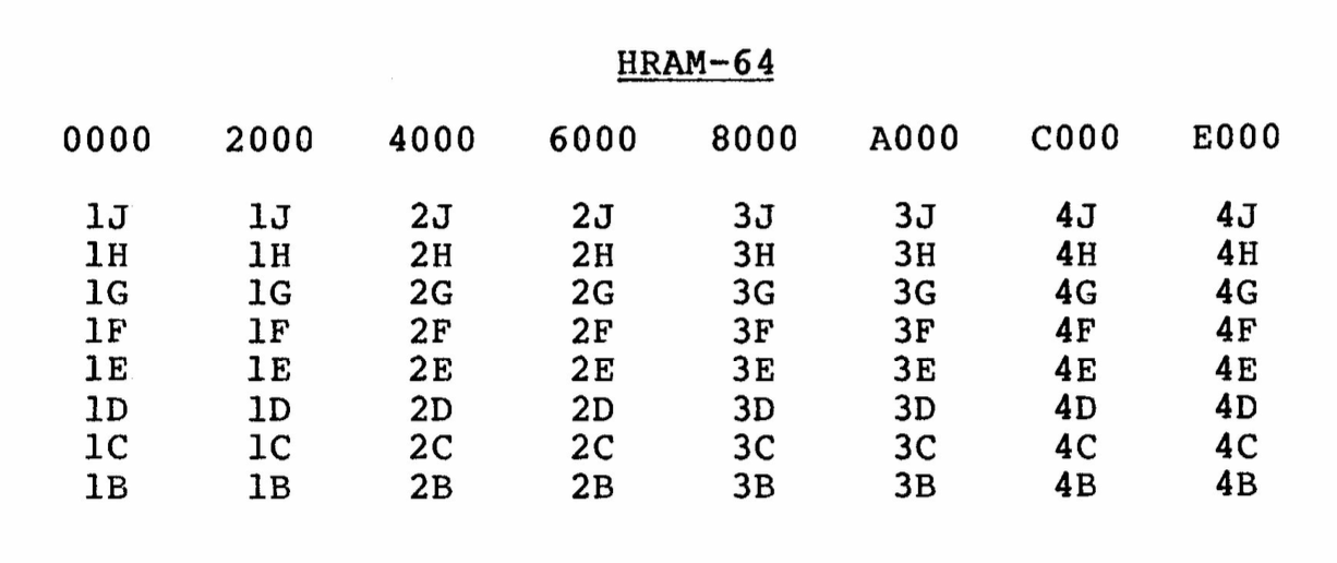
(1A-4A = parity)
FDC
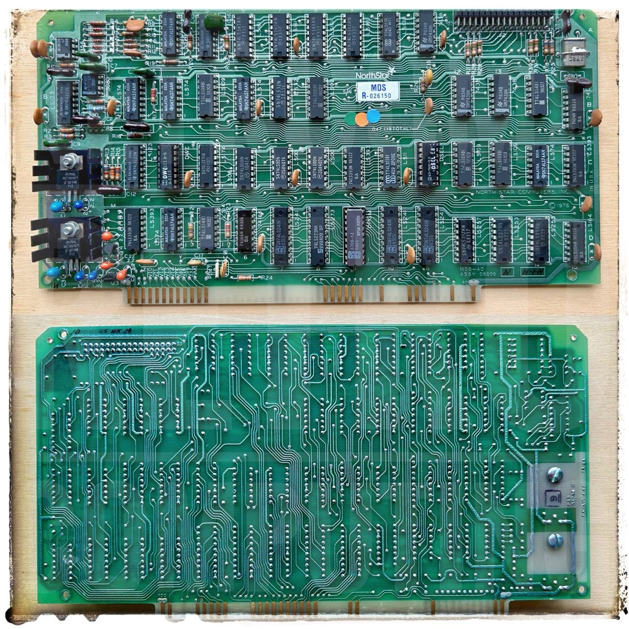
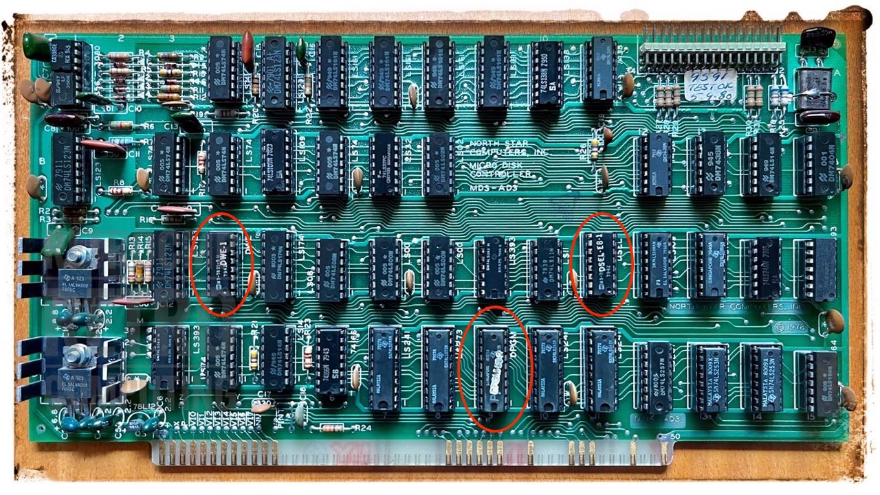
MDS-AD - Micro Disk Controller - DSDD
The original North Star MICRO-DISK System (MDS) controller is an integrated system of hardware and software.
The revisions that I know from pictures are:
- MDS-AD
- MDS-AD2
- MDC-AD3
This MDS-AD is a later floppy disk controller for the Horizon: single-sided, double-sided, FM and MFM. The very first (FM only) was the MDC-A.
MDS-AD3 - Micro Disk Controller - DSDD
The PROM (DPGM, D9) on the micro/floppy disk controller is located at address E800 by default.
On board PROM: Bootstrap software (8080/Z80 machine code) is stored in an on-board 256 byte bipolar PROM (DPGM, 9D). This PROM provides 256 bytes of memory. The 8 low order address bits address the PROMs. The PROM outputs are driven onto the Data Input Bus. [7]
The contents of the PROMs are available for download from Mike Douglas.
To the floppy disk controllers of the North Star Horizon is to be said in principle that these react in the interaction with the floppy disk drive and the hard sectored floppy disks very sensitively to deviating or fluctuating speeds. Therefore, the newer half-height ones are better than the old ones with belt drive.
The hard sectored N* is more fussy about the sectors than the Heathkit H17 was. ... The controller on the N* keeps track of the sectors by a counter. It isn't quite as fussy about 300 rpm as you might think. It does expect the drive to be up to speed in only a few sectors after enabling the drive. It has a limit on the amount of time between sectors before the controller will error out. I forget what it was but it is controlled by a crystal divider, as a counter. [8]
MDC-A4 - Micro Disk Controller - SSSD
This MDC-A is the very first floppy disk controller for the N* Horizon: single-sided (SS), single-density (SD, FM). You can not use double-density (MFM) disks.
The revisions that I know from pictures are:
- MDC-A1
- MDC-A2
- MDC-A3 (not yet seen ¯\_(ツ)_/¯)
- MDC-A4
[Herb Johnson] Confusion about Northstar MDS and MDC floppy controllers
The Northstar floppy controller board named "MDC" was a single-density controller, first sold by Northstar around 1976. It was sold as part of their "MDS" system of controller, cables, drive cabinet with power and drives, and their operating system. This was one of Northstar's first products - a floppy disk system upgrade for S-100 computers like the MITS Altair, the IMSAI, the Processor Tech SOL, and so on. That's where the MDS/MDC confusion began.
The Northstar floppy controller board named "MDS" was a single or double-density controller, first sold by Northstar around 1978. By then, they produced the Northstar Horizon S-100 system with this product; and they may well have continued to sell their packaged disk system.
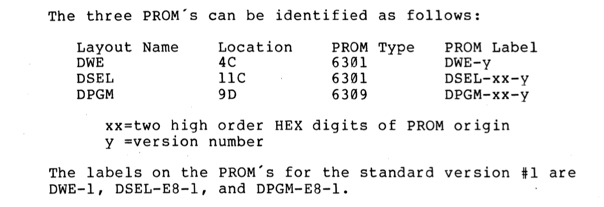
The two boards both have program PROMs; either one or two depending. They also use a PROM for address decoding. these are all small bipolar or fuse-link PROMS, easily overlooked as "logic ICs". Refer to parts lists and schematics for specifics on those PROMs. the locations of the PROMS confirm which schematics and docs "go with" which board. [16]
The contents of the PROMs are available for download from Mike Douglas.

I have removed all TTL ICs from this board and tested them with a simple IC tester (POLAR D320). Result: 1x 7438 is defective. And I checked the pins for corrosion and black tarnish. I have had very bad experiences with the TTLs from Texas Instruments. Almost without exception, the pins are tarnished black. This is silver sulfide. Silver sulfide is an electrical non-conductor and should therefore be removed.
Then I replaced the one tantalum capacitor (25V, 6.8uF) and two ceramic capacitors (473, 25V, 0.047uF). They just didn't look good any more, tarnished or already slightly chipped. Get rid of them, there's no point in keeping them. But keep the old parts.
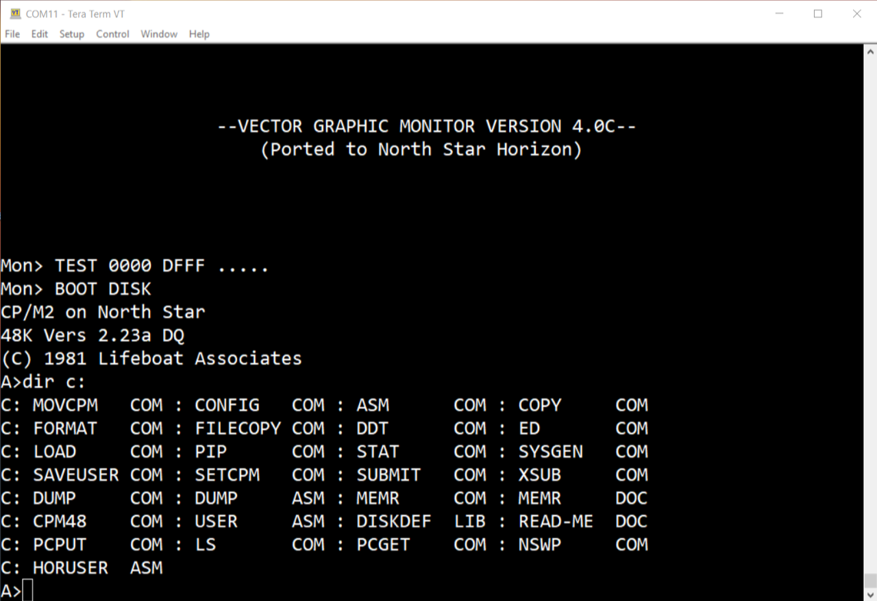
And then the chicken and egg dilemma arises again. How do I get a boot image copied to a new HS10 disk? Also, I have never been able to test this controller because I don't have a boot disk. But none of this is a problem, because Mike Douglas has done some excellent groundwork here. All you have to do is start your N* Horizon with the Vector 4.0C monitor. Now read in the PCFLOP program as Intel HEX and start it with the help of the monitor. Then you can read in the corresponding NSI image via XMODEM and copy it directly to drive A:. Then restart and ... see for yourself, it worked.
Booting a single-sided, single-density floppy disk:

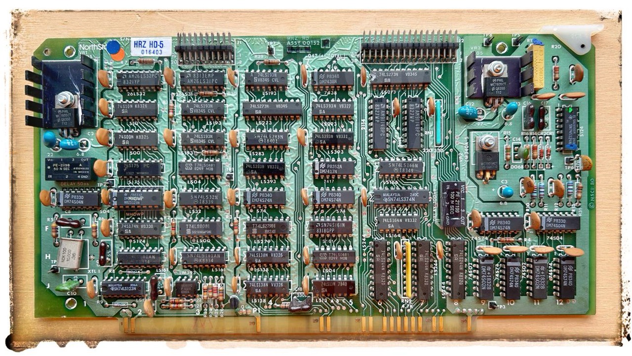
HDC
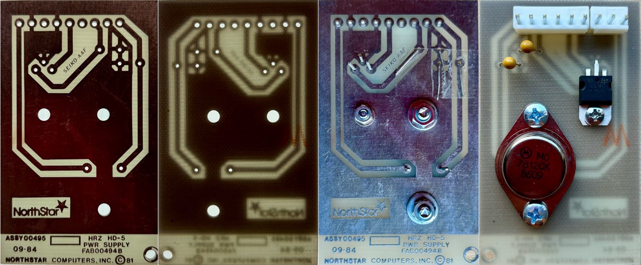
HRZ-HD-5 - Hard Disk Controller

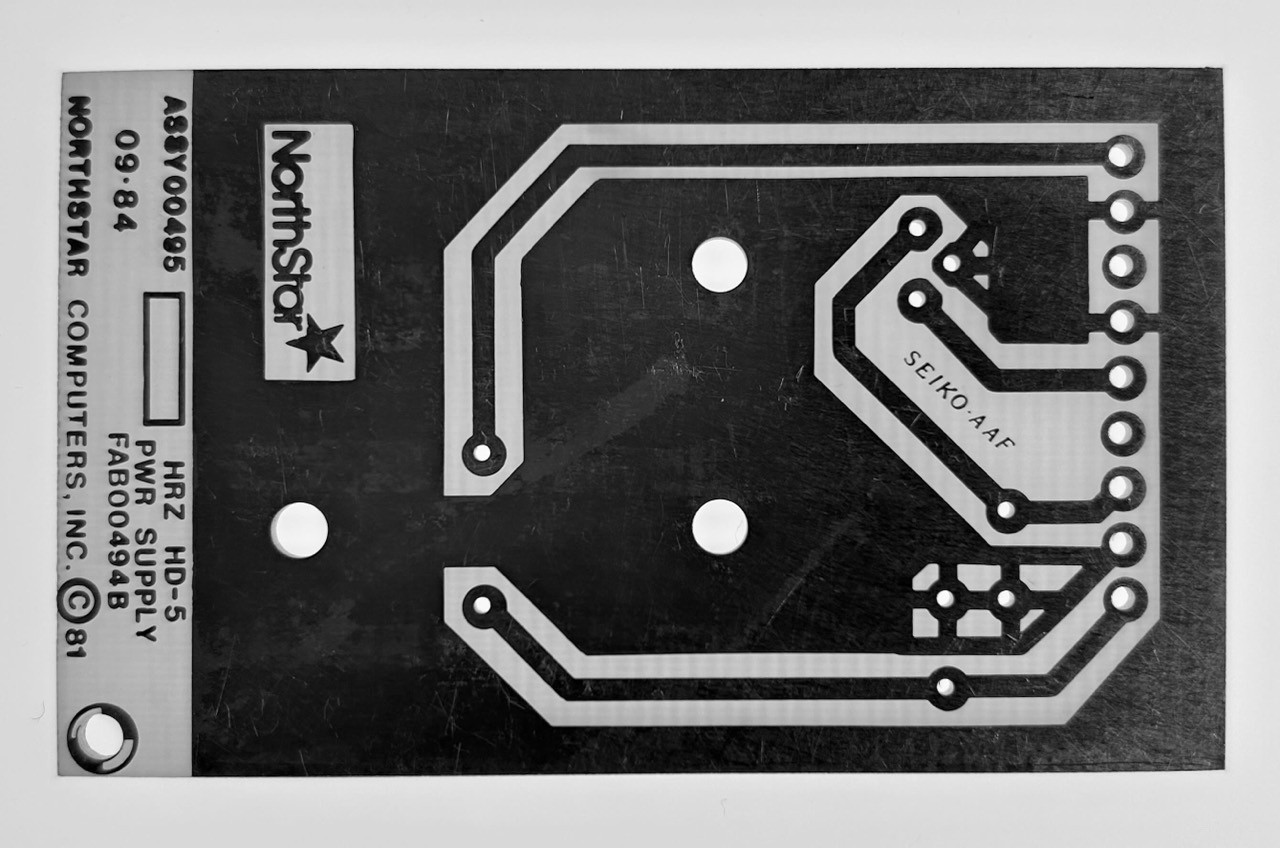
According to the information I have got from Vintage S100 Computer Enthusiasts the assembled but unsoldered PCB should look like this: TO-3 (7812), TO-220 (7805), 2x 16V 10 µF.
Downloads
Here you will find all my gathered downloads for the North Star Horizon.
Information
Here you will find all my gathered downloads for the North Star Horizon.
References
- (↑) ...
My Series About the North Star Horizon
--> Go to Part 0: Information
--> Go to Part 1 : Restoration & (my) S-100 Boards
--> Go to Part 2 : Hard-Sectored Disks
--> Go to Part 3 : File and Image Transfer
--> Go to Part 4 : PROM Modification
--> Go to Part 5 : History
--> Go to Part 6 : RAM
--> Go to Part 7 : S-100 Bus
--> Go to Part 8 : Capacitors
--> Go to Part 9 : Virtual Horizon
--> Go to Part 10 : S-100 Boards