<-- Back to Part 6: RAM
--> Go to Part 8: Capacitors
S-100 Bus
If you want to learn about the S-100 bus, you should visit Herb Johnsons website. If you have read all this, then you should be fully aware. In the mid-90s, he wrote many articles as author Dr. S-100 in The Computer Journal [2].
Unlike the later buses, the S-100 bus has evolved from the Altair to the IEEE 696 standard. In other words, S-100 is not always S-100! See below GND pins 20/70 and next!
The Altair [S-100] connectors were made with a different pin spacing than the standard 0.125-inch Texas Instruments connectors used by Imsai. You could plug the same circuit board into either type of connector, but the pins that went into the motherboard were spaced differently. [4]
PIN locations: The front of an S-100 card is the "component side". With the connector down (as if to insert), the leftmost pin is ONE, the rightmost is FIFTY. If you reverse the card to the back (generally no components), the leftmost pin is ONE HUNDRED, the rightmost is FIFTY-ONE. So pin 1 and 51 are atop each other, and in fact are connected to each other - they provide +8 volts (+5 if the bus has regulated power). Also pin 100 and 50 are atop and connected to each other, and provide GROUND. [1]
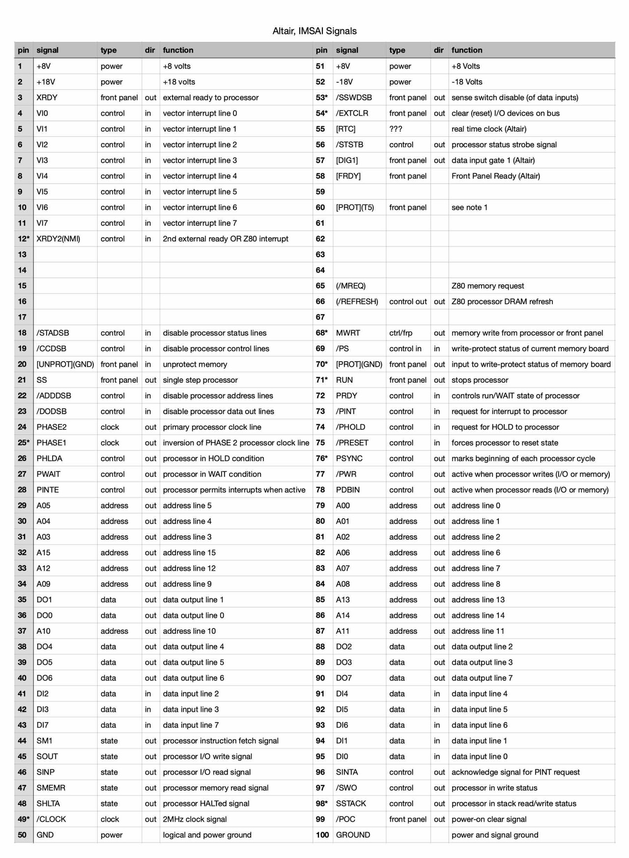
The chart below lists the "S-100 bus" signals for the Altair 8800(a), the IMSAI 8080 variations, and seperately the IEEE-696 lines. ... Active low signals are shown as "/". Unused lines are "---". Reserved lines are "rsvd". The first column are Altair 8800 and IMSAI 8080 signals; if the IMSAI signals are different they are in "()". The next column are the IEEE-696 signals. Signals 24 and 25 are named "phi" one and two. IEEE-696 signals separated by "|" represent the 8-bit and 16-bit data path signals, respectively, the latter enabled by the /SIXTN and /SXTRQ handshake. Note: Some S-100 or IEEE-696 systems may have +5V, +/-12V power, not +8 and +/-18. [1]
I have compiled the following sheets based on Herb Johnson's information.
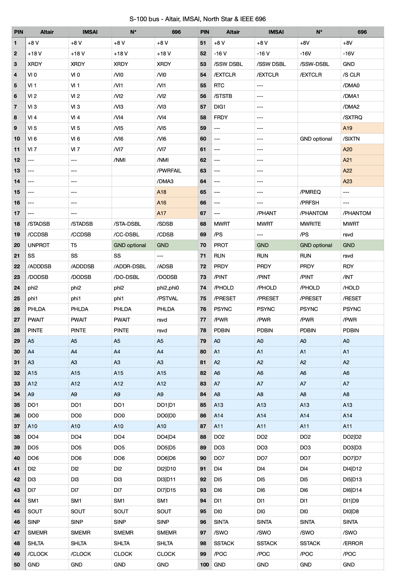
With the IEEE 696 standard, it is immediately apparent that the address lines have been increased from 16 to 24.
Pins 20/70 - GND: Front Panel
In later S-100 designs it was common to ground pins 70 and 20 - watch for this when mixing cards! [1]
Grounded pin 20 disables IMSAI front panel systems: From experience I know that when a card with grounded pin 20 is placed in an IMSAI with a front panel, the system stops working; it works again when the card is removed. The solution is dirt-simple, assisted by the fact that pin 70 (grounded on the CP-A) is immediately on the other side of the connector from pin 20. I simply put a very small piece of paper over BOTH pin 20 and 70 on the board, looping it over the edge of the edge connector; and I insert it carefully into its bus connector. Sometimes I'll put a bit of transparent tape over the paper JUST large enough to make contact on either side of the pin; but not so large as to cover the adjacent pins. The paper is not pulled off during insertion and it's held by the connector in place. [3]
Pins 68/77 - MWRT/PWR: Front Panel
The IMS 16K Static RAM has a so-called front panel option: MWR or PWR (Memory Write or Processor Write). On the S-100 bus, these are pins 68 and 77. MWR must be jumpered when used in a system with a front panel, otherwise PWR.
The memory write strobe, MWRT, must be generated somewhere in the system. It is usually generated by front panel type devices, but is optionally generated by permanent masters or mother boards in systems without front panels. Care must be taken that it is generated at only one point in a given system. [5]
External Links
Downloads
Here you will find all my gathered downloads for the North Star Horizon.
Information
Here you will find all my gathered downloads for the North Star Horizon.
References
- (↑) Herb Johnson, http://www.retrotechnology.com/herbs_stuff/s100bus.html
- (↑) The Computer Journal, #57, page 12, Sep-Oct 1992
- (↑) Herb Johnson, http://www.retrotechnology.com/herbs_stuff/s100_pin20.html
- (↑) John Monahan, http://www.s100computers.com/Hardware%20Folder/IMSAI/History/History.htm
- (↑) IEEE, Standard Specification for S-100 Bus Interface Devices, 1979
My Series About the North Star Horizon
--> Go to Part 0: Information
--> Go to Part 1 : Restoration & (my) S-100 Boards
--> Go to Part 2 : Hard-Sectored Disks
--> Go to Part 3 : File and Image Transfer
--> Go to Part 4 : PROM Modification
--> Go to Part 5 : History
--> Go to Part 6 : RAM
--> Go to Part 7 : S-100 Bus
--> Go to Part 8 : Capacitors
--> Go to Part 9 : Virtual Horizon
--> Go to Part 10 : S-100 Boards