I EXPLICITLY WARN YOU THAT YOU MAY PERMANENTLY DESTROY YOUR HARDWARE IF YOU MAKE ANY TECHNICAL CHANGES TO IT. I DO NOT ACCEPT ANY RESPONSIBILITY OR LIABILITY WHATSOEVER IF YOU CARRY OUT MODIFICATIONS TO YOUR HARDWARE ON THE BASIS OF MY PERSONAL TECHNICAL DOCUMENTATION. IF YOU MAKE ANY MODIFICATIONS TO YOUR HARDWARE, YOU DO SO AT YOUR OWN RISK. ALWAYS ENSURE THAT THE PLUG CONNECTIONS ARE CORRECTLY SEATED. EVEN TOUCHING SENSITIVE COMPONENTS SUCH AS CPU, RAM, ... CAN CAUSE THEM TO BE IRREVOCABLY DESTROYED (ELECTROSTATIC DISCHARGE - ESD).
WITH MANY OLD COMPUTER POWER SUPPLIES, VOLTAGE IS STILL APPLIED TO COMPONENTS EVEN WHEN THE SWITCH IS IN THE OFF POSITION.
!!! WARNING !!!
PC-34 to Shugart-50 Adapter
With the adapters presented here you can connect an old 8" drive with Shugart 50 pin interface to a "modern" IBM compatible floppy controller with PC 34 pin interface.
Important: However, there is also another type of adapter that looks the same at first glance but has a fundamentally different internal wiring. You need this type if you want to connect a "modern" floppy disk drive (5.25" or 3.5") to an „old“ 50 pin floppy disk controller (like Tandy/Radio Shack; not IBM compatible).
Mark J. Blair: Adapt 34 Pin Floppy Drives to 50 Pin Controllers
Frank Durda IV: Utilizing 5.25" or 3.5" media on your Tandy/Radio Shack computer system. Wayback machine; the original website is down, Frank Durda IV died in 2018.
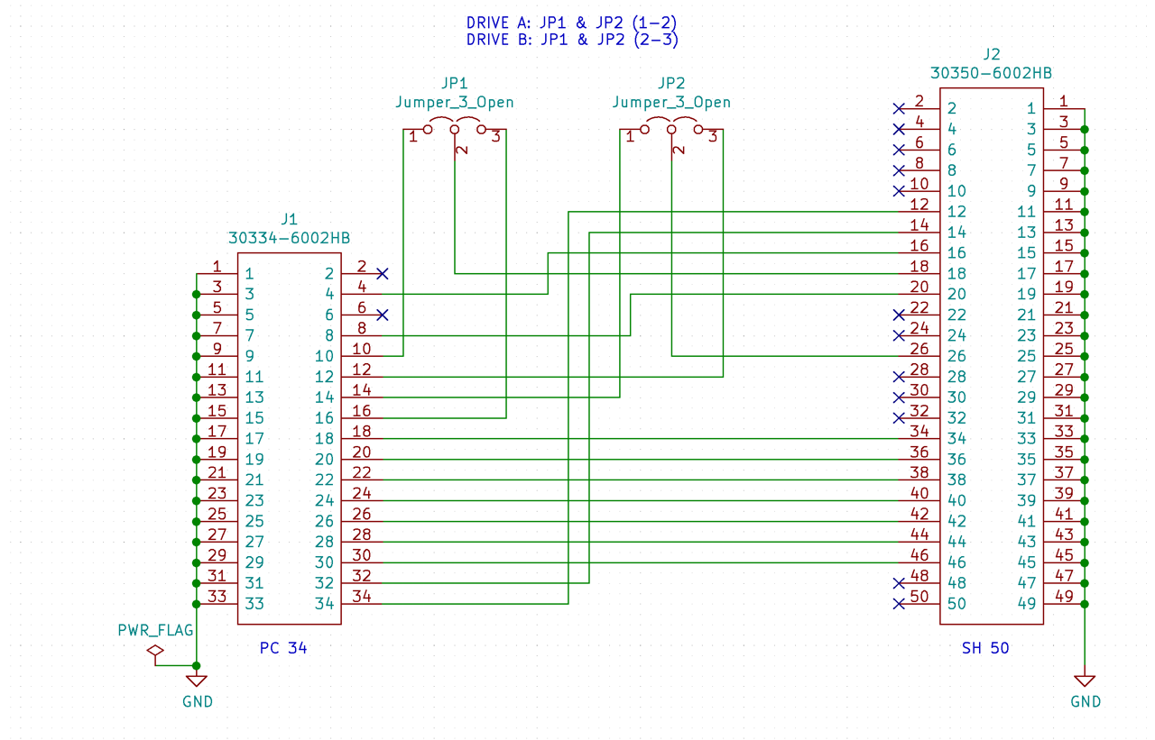
My adapters are based on the following assignment of signals.

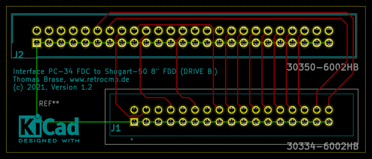
Version 1.2
Status: Tested, 08.03.2021 (80286-12 VLSI, CompatiCard I, Y-E DATA YD-180-1601)
JLCPCB
Currently in production. Let's see if the PCB really works! The PCBs are scheduled for delivery on 08.03.2021. I will report later.
Arrived today, 08.03.2021 as announced. Unpacked, soldered on both plugs, tested and ... the adapter works. Hooray!
Here, however, without the logo. I added this again after the order. ¯\_(ツ)_/¯
And what can I say. The price is extremely good. I paid only 2 EUR for five PCBs; shipping 10 EUR. Customs duties were not incurred for this small invoice amount. The PCB is easy to solder. What more could you want.

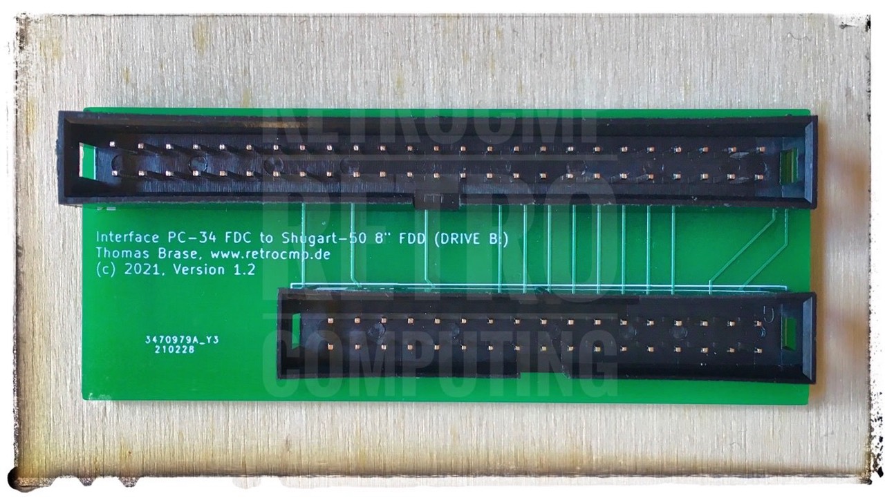
with „Low Profile Header"
Usage
- Use a standard twisted PC floppy cable (ie. drive A: connected AFTER the twist and drive B: BEFORE the twist).
- Jumper the 8" drive as the 1st drive (DRIVE SELECT 1, SH 50 pin 26), see figure 4. All other DS signals are not routed by this interface, so DS1 must always be jumpered on the 8" drive; DS2-4 are a dead end.
- Connect the interface (Shugart-50) to the 8" drive using a suitable 50-pin cable and the appropriate adapters.
- Connect the interface (PC-34) with the PC floppy cable header ...
- .... AFTER the twist. Then the 8" drive will be assigned as DOS drive -> A:
- ... BEFORE the twist. Then the 8" drive will be assigned as DOS drive -> B:
IMPORTANT NOTE: Do not be confused by the label „DRIVE B:“ on the circuit boards. The label „DRIVE B:“ has nothing to do with the later drive assignment under DOS! The label „DRIVE B:“ refers solely to the two signals DRIVE_SELECT_B and MOTOR_ENABLE_B, see figure 4. Yes, I know this is a bit confusing!

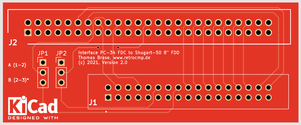
Version 2.0
Status: Ordered at JLCPCB, 11.03.2021 (RED); tested: 26.03.2021 (80286-12 VLSI, CompatiCard I, Y-E DATA YD-180-1601)
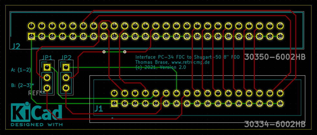
The interface works perfectly. The two jumpers give you the choice of placing the 8" drive either on A: or on B:. The 8" drive ALWAYS remains jumpered to DS1!

with „Low Profile Header"
Usage
- Use a standard twisted PC floppy cable (ie. drive A: connected AFTER the twist and drive B: BEFORE the twist).
- Jumper the 8" drive as the 1st drive (DRIVE SELECT 1, SH 50 pin 26), see figure 4 & 7. All other DS signals are not routed by this interface, so DS1 must ALWAYS be jumpered on the 8" drive; DS2-4 are a dead end.
- Connect the interface (Shugart-50) to the 8" drive using a suitable 50-pin cable and the appropriate adapters.
- Option 1: according to V1.2
B: JP1 (2-3), JP2 (2-3)
Connect the interface (PC-34) with the PC floppy cable header ... - .... AFTER the twist. Then the 8" drive will be assigned as DOS drive -> A:
- ... BEFORE the twist. Then the 8" drive will be assigned as DOS drive -> B:
- Option 2:
A: JP1 (1-2), JP2 (1-2)
Connect the interface (PC-34) with the PC floppy cable header ... - .... AFTER the twist. Then the 8" drive will be assigned as DOS drive -> B:
- ... BEFORE the twist. Then the 8" drive will be assigned as DOS drive -> A:
With these two jumper options, you are very flexible with your floppy cable and your drive assignment.
Version 2.1
Status: Ordered at JLCPCB, 12.03.2021 (BLUE); tested: 26.03.2021 (80286-12 VLSI, CompatiCard I, Y-E DATA YD-180-1601) Note: This interface may not fit every 8" drive! This has to do with the arrangement and position of the 8" FDD card edge.
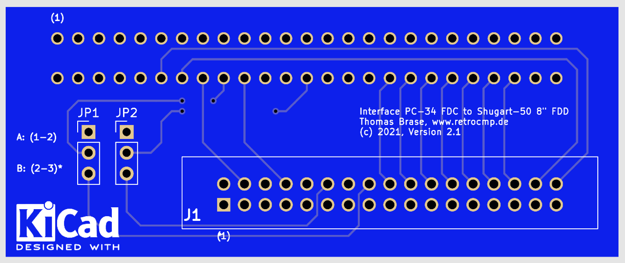
Special note: Unfortunately, I made a small "design" error here. The card edge connector should actually be on the other side. But this is not possible, of course, because otherwise the connection to the 8" drive is wrong. The attentive observer will see this immediately in figure 8. The footprint is wrong! Remedy: Simply solder on the edge connector from the front (as shown in fig. 8a) and everything is fine again. Line (1) is correct shown in fig. 8.

with „Low Profile Header" and „Card Edge Connector“
Usage
- Use a standard twisted PC floppy cable (with drive A: connected AFTER the twist and drive B: BEFORE the twist).
- Jumper the 8" drive as the 1st drive (DRIVE SELECT 1, SH 50 pin 26), see figure 4 & 7. All other DS signals are not routed by this interface, so DS1 must ALWAYS be jumpered on the 8" drive; DS2-4 are a dead end.
- Connect the interface (Shugart-50) to the 8".
- Option 1: according to V1.2
JP1 (2-3), JP2 (2-3)
Connect the interface (PC-34) with the PC floppy cable header ... - .... AFTER the twist. Then the 8" drive will be assigned as DOS drive -> A:
- ... BEFORE the twist. Then the 8" drive will be assigned as DOS drive -> B:
- Option 2:
JP1 (1-2), JP2 (1-2)
Connect the interface (PC-34) with the PC floppy cable header ... - .... AFTER the twist. Then the 8" drive will be assigned as DOS drive -> B:
- ... BEFORE the twist. Then the 8" drive will be assigned as DOS drive -> A:
With these two jumper options, you are very flexible with your floppy cable and drive assignment.
Gerber Files, BOM, and Ordering
Version 1.2
- Gerber files: .... Download
- Ordering PCBs: ... JLCPCB
- Ordering PCBs: ... OSHPark (shared project)
- BOM: ............. Mouser (PDF)
Version 2.0
- Gerber files: .... Download
- Ordering PCBs: ... JLCPCB
- Ordering PCBs: ... OSHPark (shared project)
- BOM: ............. Mouser (PDF)
Version 2.1
See special note above!- Gerber files: .... Download
- Ordering PCBs: ... JLCPCB
- Ordering PCBs: ... OSHPark (shared project)
- BOM: ............. Mouser (PDF)
External Links
- Information and download: KiCad
Information
- Getting started in KiCad (22.02.2021, PDF)